Week 8 - Challenge 3 - Coin Holder Design
Week 8 - Challenge 3 - Coin Holder Design
AIM:-
Create the Coin Holder Plastic component through the given Class-A surface. To begin with, the tooling axis for the given Class-A Surface should be created meeting the requirements of the draft angle and at the end perform the Draft analysis on the model.
Take the Thickness of the component to be 2.5 mm
CLASS A-SURFACE-
FIRST CREATE TOOLING AXIS
- The direction in which the mould open and closes is called the tooling axis direction.
- Check the connectivity of the surface and ensure there will be no gap between the surfaces and then define the tooling axis.
- While creating a tooling axis please ensure to give the tooling axis on a flat length surface or the surface which have a hole on it.
- Create a point on the middle of the base surface by using point on the surface command then create a intersection for the surface and extract the reference lines which will be helpful for creating the dummy tooling axis using the intersect method by creating a bisecting line..
- Use the line command and draw the lines which is aligned with the extracted lines and extended it to the required length.
- But in this surface one side wall is right angle and other is tillted thats why use simple rule to create a tooling axis first check the plane surface and then extract them and create a line in y-direction thats line is called the tooling axis.
DRAFT ANALYSIS OF CLASS-A-SURFACE-
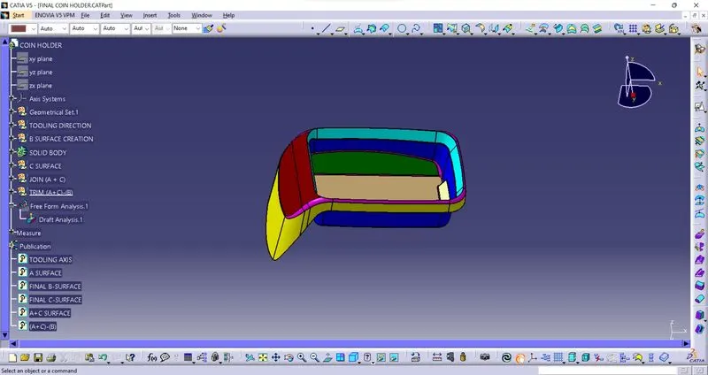
SECOND CREATE B-SURFACE-
- In the case of Class A the surface below is called core and the surface above is called cavity.
- Class A is an aesthetics surface and class B is an engineering surface
- B surface can be divided into four surfaces the side walls, top walls, outer flange and the base surface and later trim them altogether.
- First step is to create the side wall surfaces by extracting the required surface from Class A and untrimmed it thus we will get a single surface which will be extrapolated to get the required size and finally offset it to the inner side of class A as per the thickness of the material and trim them together and apply the required fillet by measuring the values from class A.
- Base surface of the component is then extract, untrimmed, extrapolated, offset and trimmed.
- The top walls can be directly extrapolated from the extracted surfaces and offset it for the required size of the material.
- Then join the base, side wall and top wall by trim operations.
- As the Outer flange is surface complex it can be divided into two parts and extract them then go for extrapolation, offset, split and join operations and finally check the for the connectivity by intersecting method.
- Now all the four geometries are trimmed together to get the B surface.
- Fillet is applied to the required surfaces by measuring the fillet value from the class A surface.
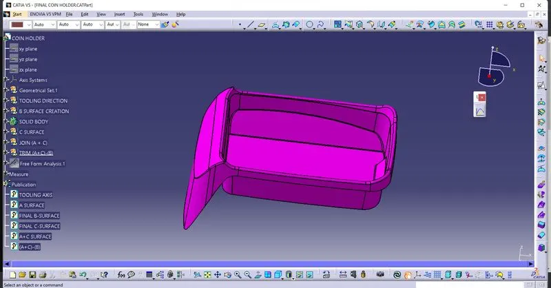
THIRD CREATE C-SURFACE-
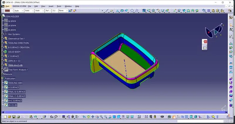
- C surface has been created from the boundary lines of class A surface and by extracting the supporting surfaces then sweep the boundary lines with reference to the extracted surfaces.
- In order to get the C surface first we have to create a boundary lines of class A surface or by using multiple extrapolated command and check for the continuity of it.
- Create a sweep with reference to the curve and the reference surface with a 90 degree angle and give the inside direction Check for the continuity of the surfaces if there is any gap go for extrapolated and trim all together now we will get the class C surface.
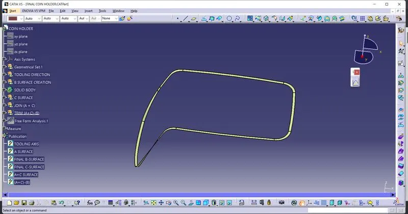
FOURTH JOIN (A+C) SURFACE-
Then join the class A surface and C surfaces together by join command(merging distance 0.001-0.003) then check it for connectivity of the surfaces.
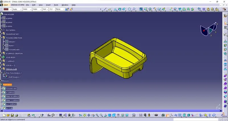
FIFTH TRIM B-SURFACE FROM (A+C) SURFACE-
Trim the B-surface from the (A+C)-surface and we get the final suraface.
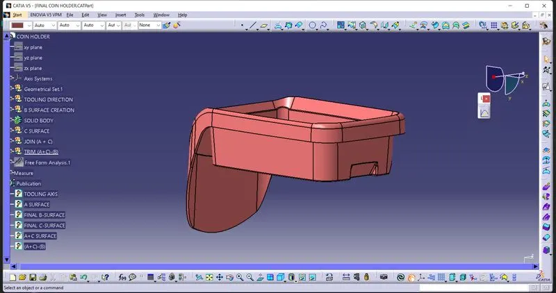
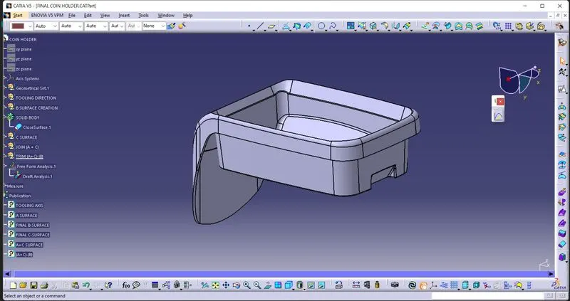
Now we check the boundary should be closed with the help of boundary command and then go the part design and use the closed surface command and we get the solid body.
SOLID BODY-
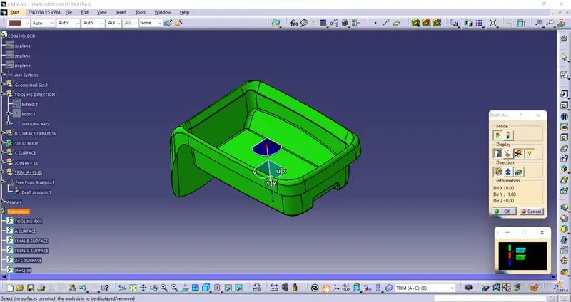
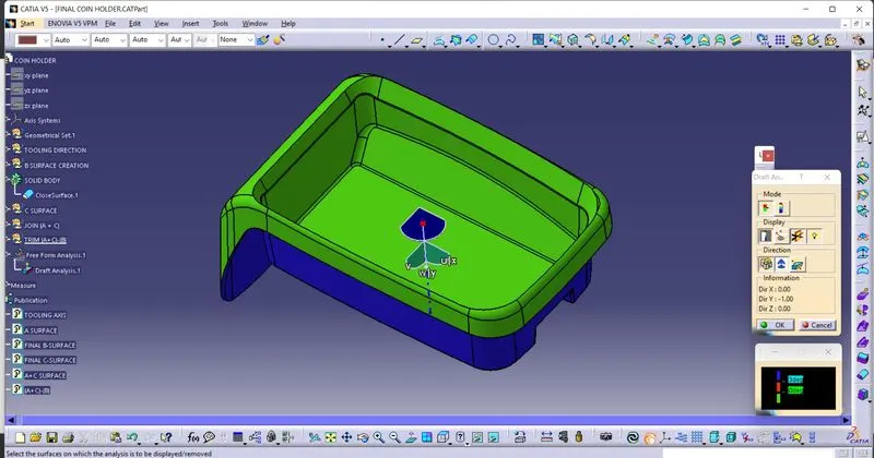
DRAFT ANALYSIS-
First check the material mode and then give the draft command for draft analysis with max (3 degree).
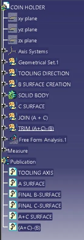
GEOMETRICAL TREE STRUCTURE-
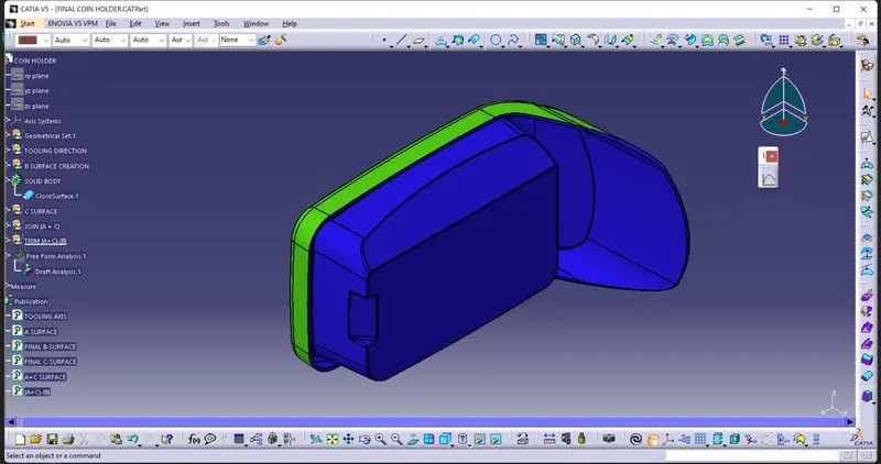
ISOMETRIC VIEW-
FRONT VIEW-
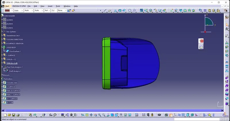
SIDE VIEW-
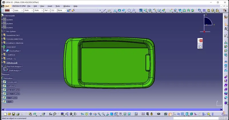
TOP VIEW-
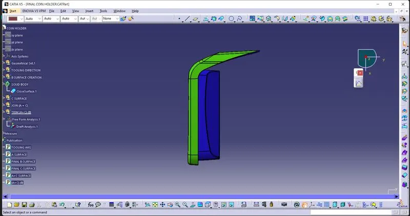
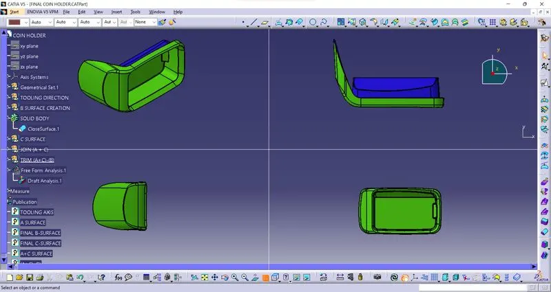
ALL VIEW IN ONE FRAME-