Week 8 - Challenge 3 - Coin Holder Design
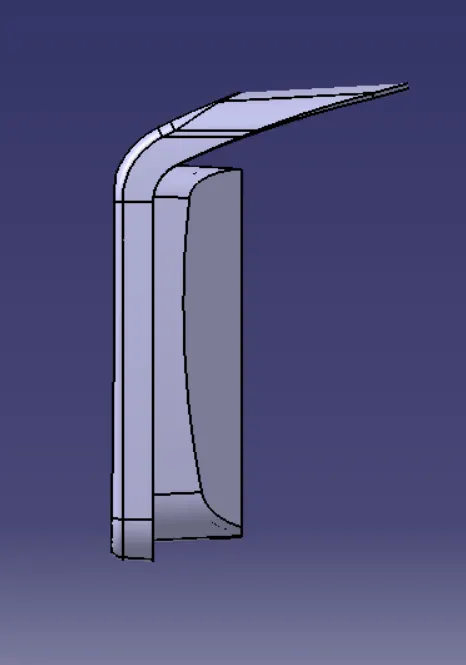
STEP 1 - Use the provided class A surface to create the coin holder design
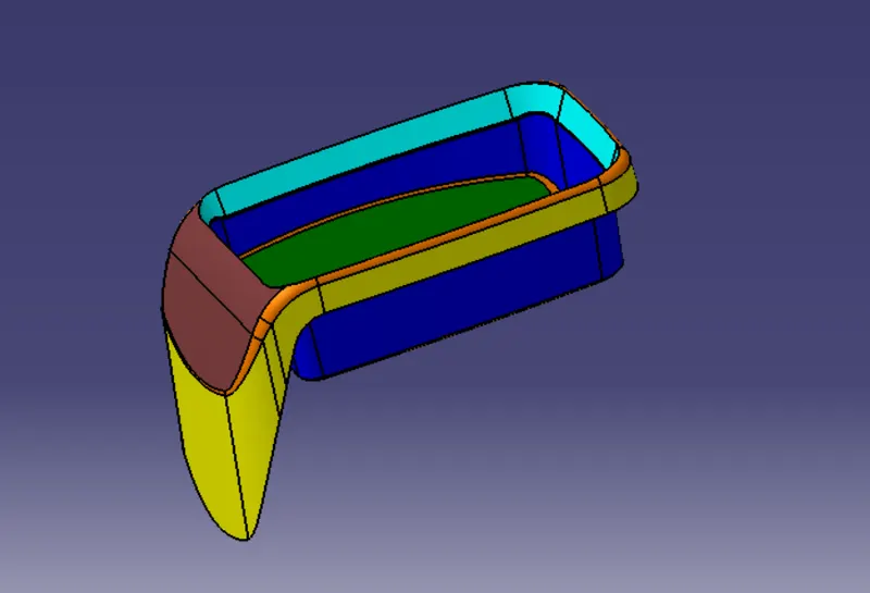
STEP 2 - CREATING TOOLING AXIS
The tooling axis is made by making a point on the surface, generating a line with respect to that point, considering the general shape and the corners, and then making the tooling axis line from those surfaces.
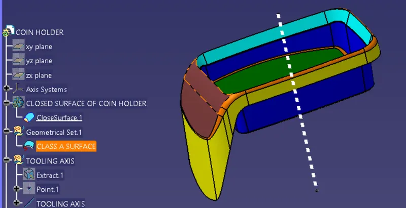
STEP 3 - CREATION OF CLASS B SURFACE
The class B surface is produced using the class A offset command. Since the class A surface contains fillet sections, the radial surfaces must first be extracted, untrimmed, and linked with perpendicular pieces before the final radius can be determined.
The fillet is provided based on the offset distance after taking into account all of the corner, edges, and radius.
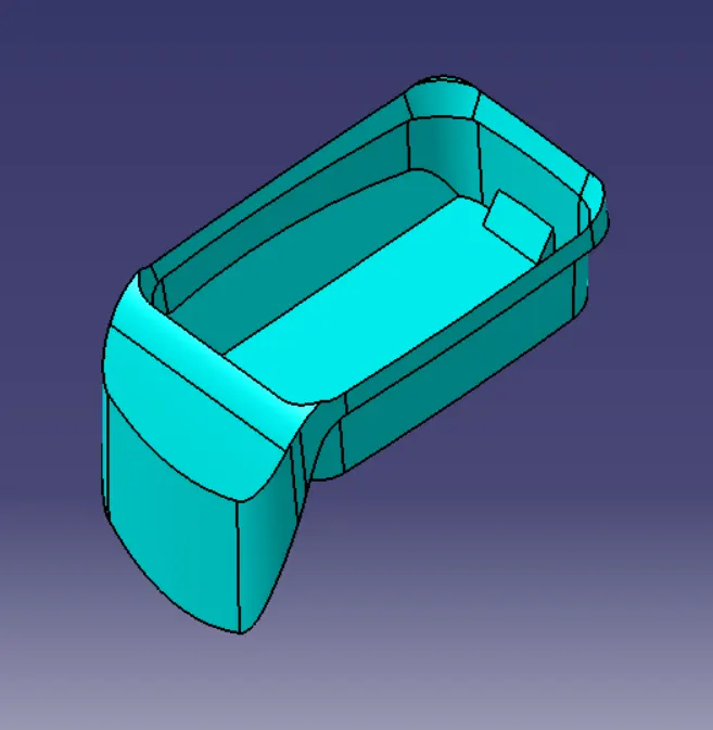
STEP 4- CLASS C CREATION
The class c surface is generated perpendicular to the axis, linking both A and B, passing b surface from A surface, and is not directly related to the ejection or the tooling axis. No alterations have been made to A Surface's outer edges; only changes have been made to B Surface.
The reference curve and support are used to construct the c-surface, which is at a 90° angle to the B surface.
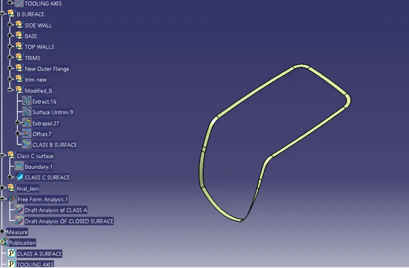
STEP 5- FINAL TRIM OF SURFACE
Before trimming it with the B surface, the C surface is linked to the class A surface.
To generate the finished result, the connected surface is then trimmed with the B surface.
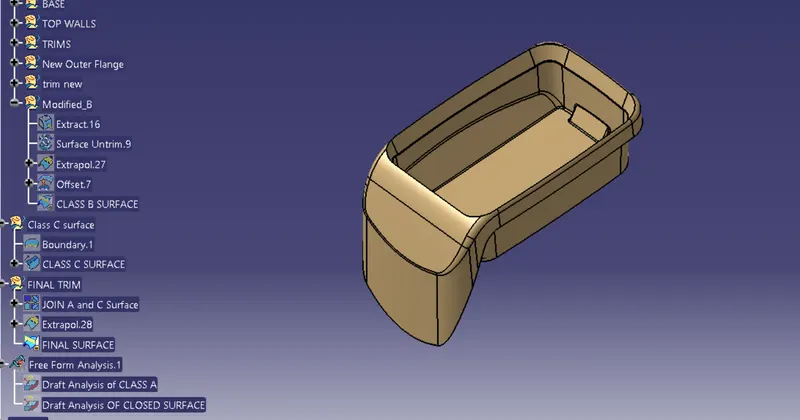
STEP 6 - Once finished, the surface part is examined for any boundaries, and if everything is okay, the close surface command is used to convert the surface part into the part body.
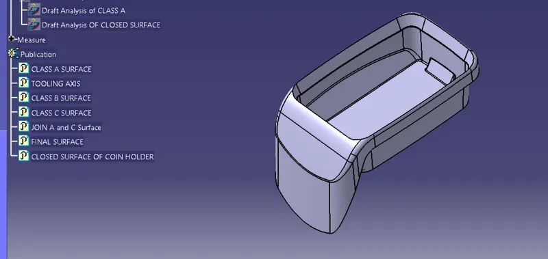
STEP 7 - DRAFT ANALYSIS OF CLASS A AND FINAL SURFACE
DRAFT ANALYSIS-
You may easily acquire the draft angle using manual measurements on several surfaces with the aid of the draft analysis. Change your shading style to "Shading with Material" as your initial step. The Draft Analysis icon in the Analysis toolbar must then be selected as the next action. The draft analysis begins with a direction along the Z-axis. You can accomplish this by dragging the compass in the direction of the Tool axis. With the draft direction fixed, you may use the "on the fly" mode to collect the draft angles along various surfaces. Simply turn on the symbol in the dialogue box for the draught analysis, then move your cursor over the area. Check the color variation in the part and examine the draught angles using the "invert draft direction method." now satisfied with this position, lock the orientation.
CLASS A DRAFT ANALYSIS
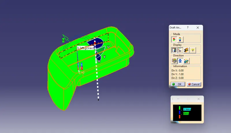
FINAL SURFACE DRAFT ANALYSIS
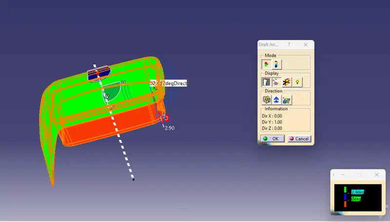
Based on a draft analysis, every component can be removed from the tool with ease.
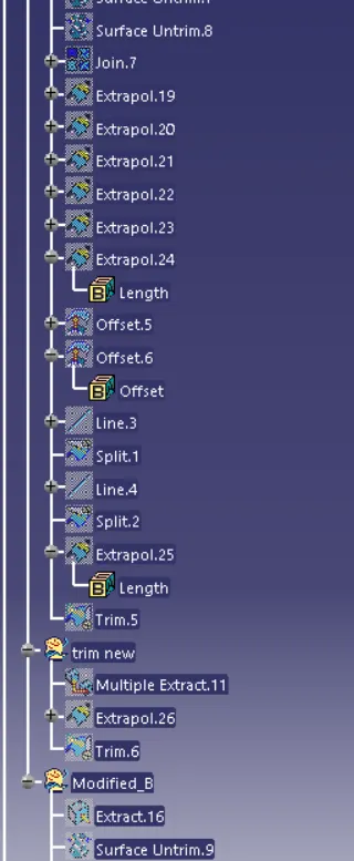
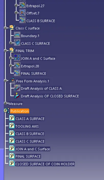
Tree structure and geometrical sets:
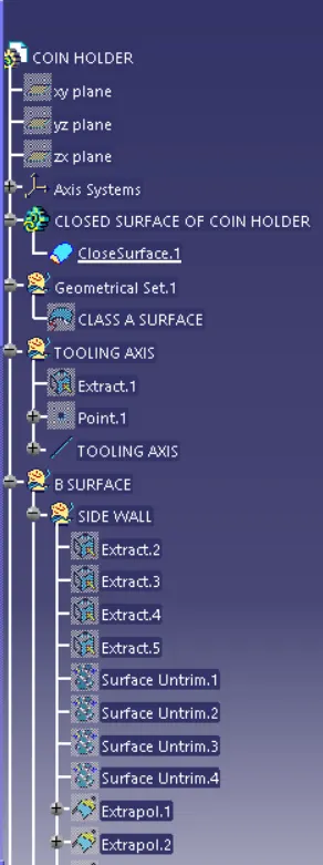
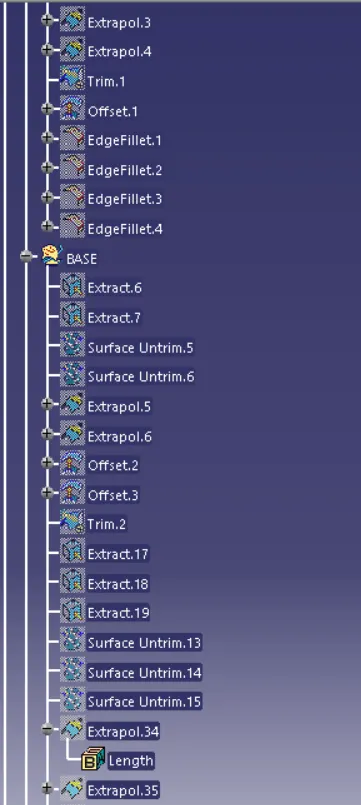
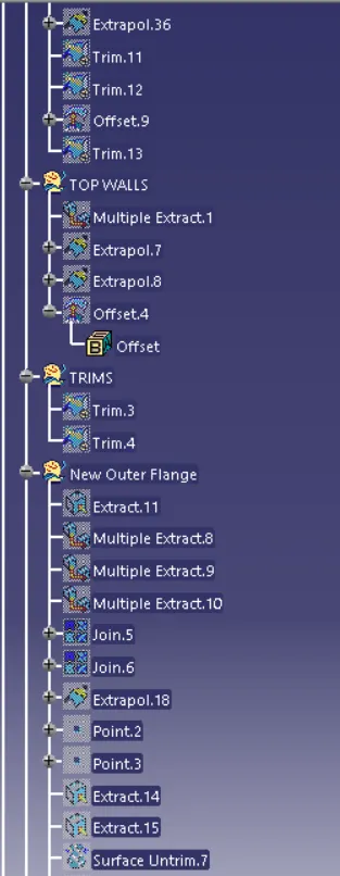
Screenshots of the solid model with the proper color code of the draft angle in various orientations (Isometric, Front, Side, and Top View)
Isometric view
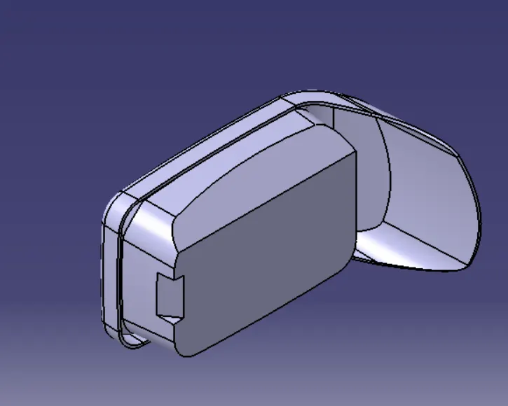
Front View
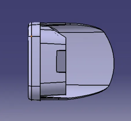
Side View
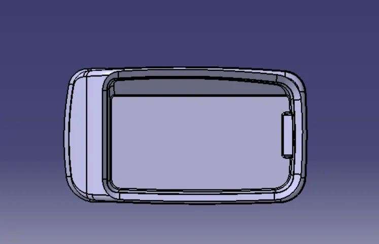
Top View