Week 8 - Challenge 3 - Coin Holder Design
TOOLING AXIS:
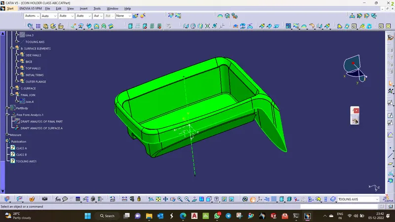
By default, if we have a hole or bin in part, we can create a tooling axis at the center point along the mold opening direction.
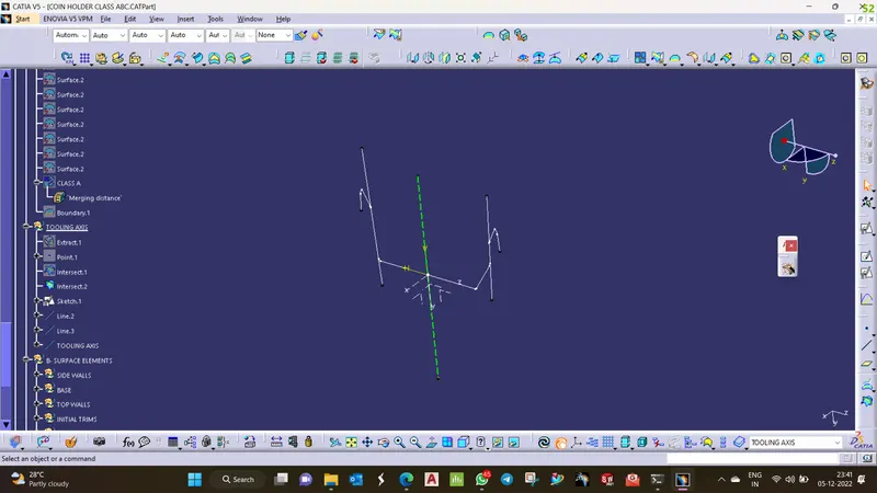
- Create a point by extracting the base surface, point location x,y,z =0
- Create an axis system on the point at the center.
- Using the intersection command with the first element as A surface and 2nd element as YZ plane form the intersection curves.
- now extend the lines on both sides of the vertical lines of the side walls using the point-point method.
- Now using the bisect line command, create a bisecting line along the y-axis using the side wall lines as reference.
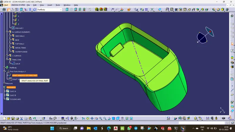
- The newly formed center line is the tooling axis, publish the tooling axis (Purple colored dotted line)
- Now create a line using point-direction along the Y direction.
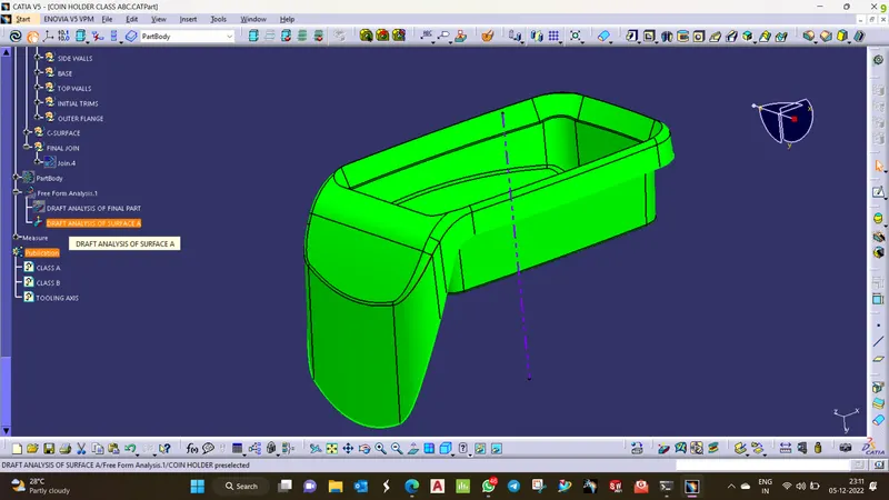
DRAFT ANALYSIS OF A SURFACE
- Change the view mode to customize and choose the material option.
- Click the draft analysis command, pick the compass and place it on the tooling axis line, lock the position.
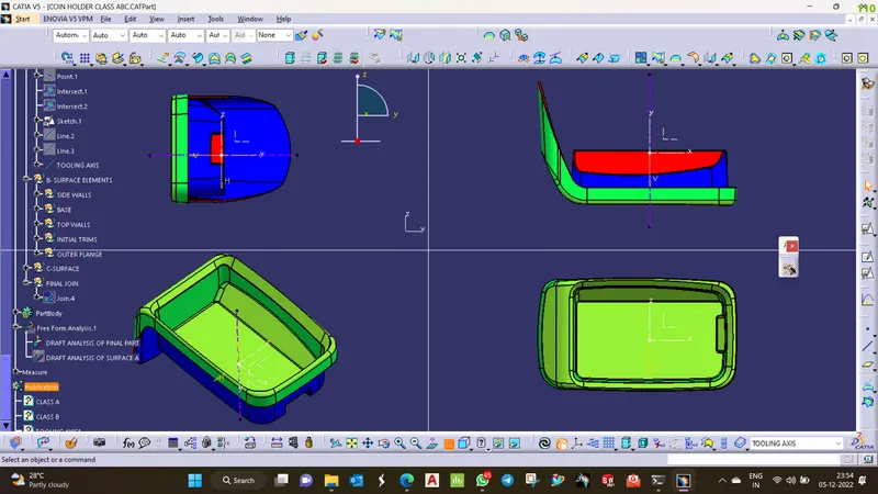
- Inverse the draft direction to show the nominal draft 3 degrees applied on the A surface.
- Using Analyse under the running point command check for the draft values all around the surface area for the required draft value.
- If the required draft value is met by the A surface, Give OK.
DRAFT ANALYSIS OF THE FINAL PART
- Change the view mode to customize and choose the material option.
- Click the draft analysis command, pick the compass and place it on the tooling axis line, lock the position.
- Inverse the draft direction to show the nominal draft 3 degrees applied on the A surface.
- Using Analyse under the running point command check for the draft values all around the surface area for the required draft value.
- Change to the full analysis mode to view the draft values for the different areas of the parts.
- If the required draft value and above is met, Give OK.