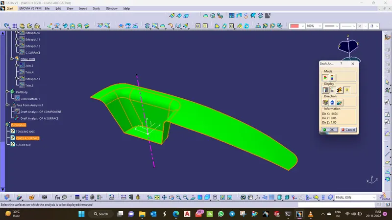
Week 8 - Challenge 2 - Switch Bezel Design
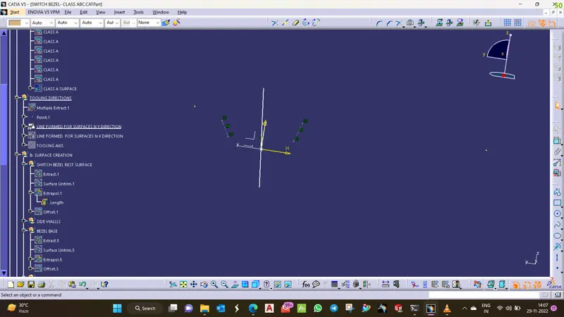
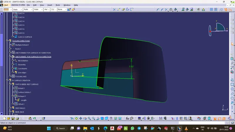
TOOLING AXIS
- TOOL DIRECTION ALONG X DIRECTION- Created by the sketch on ZX PLANE and cut part by sketch plane (ZX), create intersection using the chosen plane and then draw a line on the intersection, convert the intersection to construction line. From the center point draw line and constraint the sketch by an angle of 5.95 °
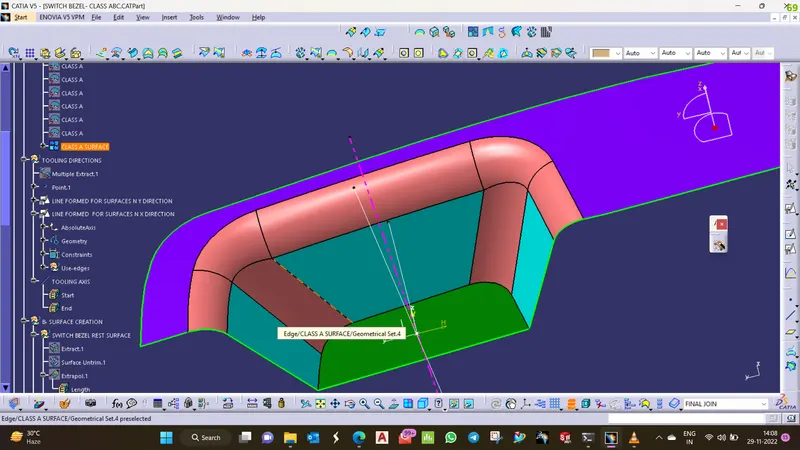
- TOOL DIRECTION ALONG Y DIRECTION- Create a point on the base surface by extracting the surface, now create an axis system on the point created on the surface to form an intersection of surfaces through the Y direction. Choose the YZ plane and draw two inclined lines on the intersection sketch, then convert the intersection to construction lines, using the two sketches, create the bisect lines.
- Now using the Tool direction lines along X and Y form the bisecting line passing in the Z direction and that will be the final Tooling axis( Pink colored dotted lines).
DRAFT ANALYSIS:
- Change the view mode to material by updating it to customize and selecting the material option
- Then click the feature draft analysis command, draft analysis dialog box opens.
- Click the compass option, pick and place the compass on the component and lock the position of the compass
- Check for the required draft value and adjust the tooling to achieve the required draft value and press OK.
DRAFT ANALYSIS OF COMPONENT
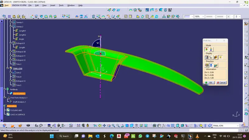
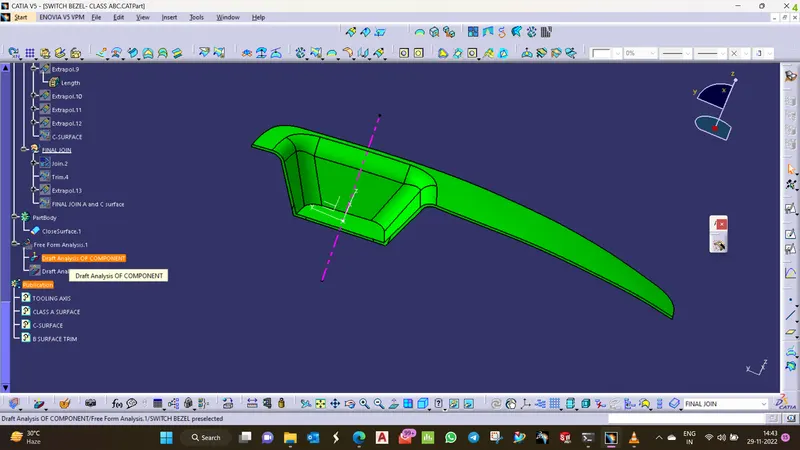
DRAFT ANALYSIS OF A SURFACE