Week 8 - Challenge 3 - Coin Holder Design
COIN HOLDER DESIGN
- AIM -
Create the Coin Holder Plastic component through the given Class-A surface. To begin with, the tooling axis for the given Class-A Surface should be created meeting the draft angle requirements and performing the draft analysis on the model at the end.
- METHODS AND PROCEDURE FOLLOWED -
Take the Thickness of the component to be 2.5 mm
- Creating a Tooling Axis
- Creating a Class B & C surface
- Building a solid body using a close surface
- Building a solid body by using a closed surface
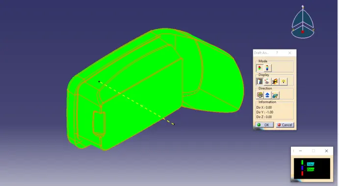
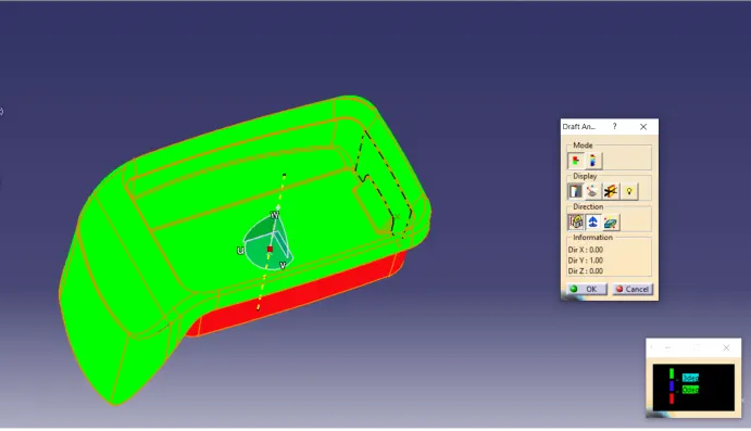
- Performing a draft analysis
- It was ensured that the given Class A surface was in a single boundary using the boundary command and made an intersection.
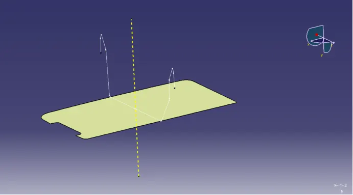
- Creating a tooling axis by steps as given below -
- Extract a base surface
- Make a point on a surface by zero coordinates.
- Then make a line from that point in the Y direction
- The tooling axis is formed and named in a geometrical set
- Creating a Class B surface from a given Class A surface -
- Followed the process for making a Class B surface as given below,
- Extract it separately
- Untrim it
- Extrapolate it then made an offset of 2.5mm.
- Base -
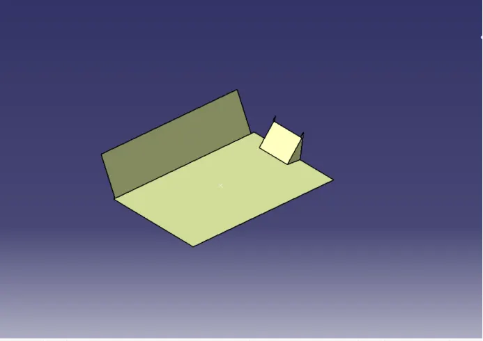
Repeated this process for all the side walls and then for the outer flange.
- Side walls -
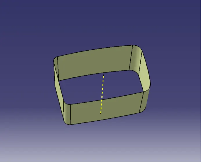
- Outer flange -
The outer flange should be offset in an inward direction.
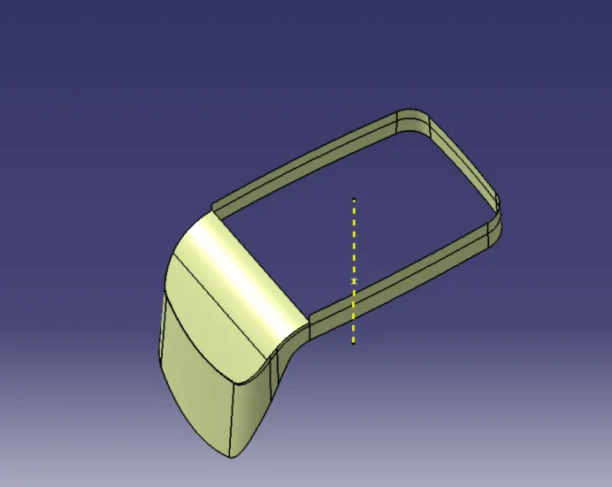
4. Initial Trim -
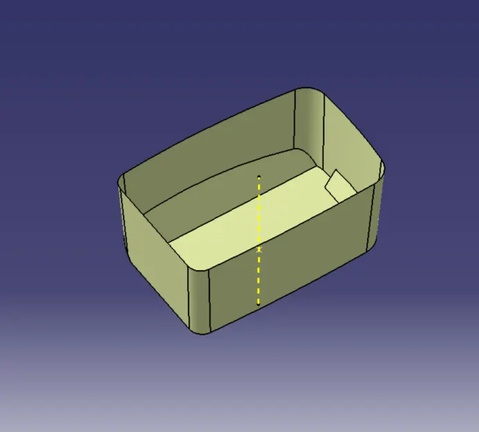
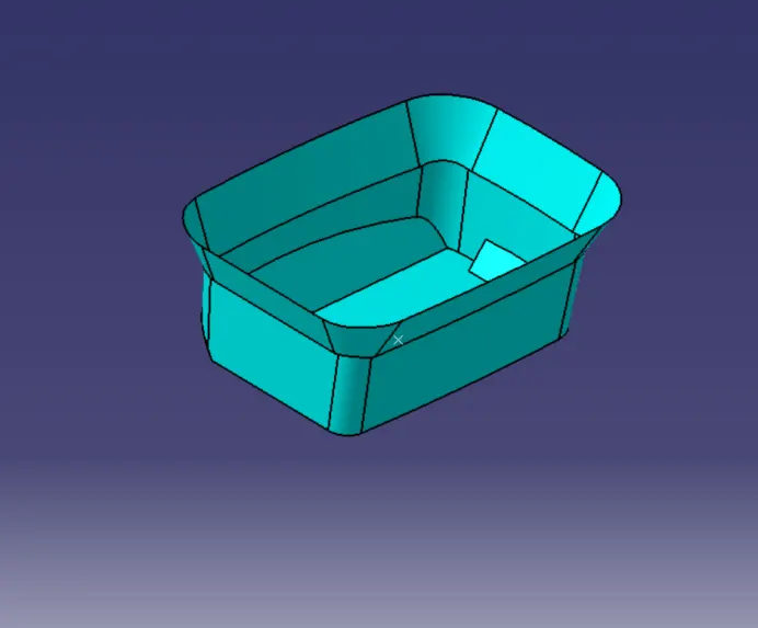
After completing all this process separately on surfaces give a trim in a separate geometrical set and name it as an initial trim.
Give edge fillets where it is required by measuring the value from a class A
- Creating a Class C surface from Class B -
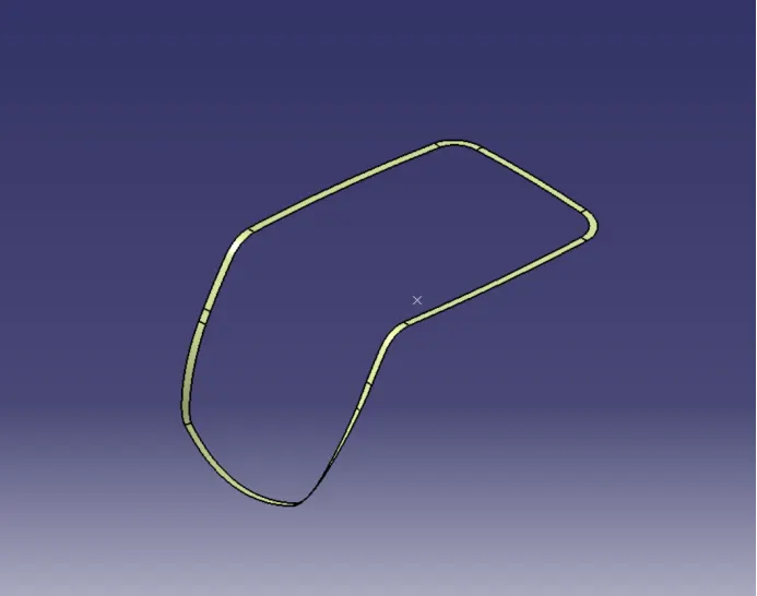
Extract the boundary of an outer flange and hole which is mounted on a side wall by multiple extracts.
Also, extract the surface which is connected with the boundary curve.
And here we get a Class C surface as given shown in the below image
- Final trim -
After getting all Class A, B & C surface
First, join a Class A and C surface
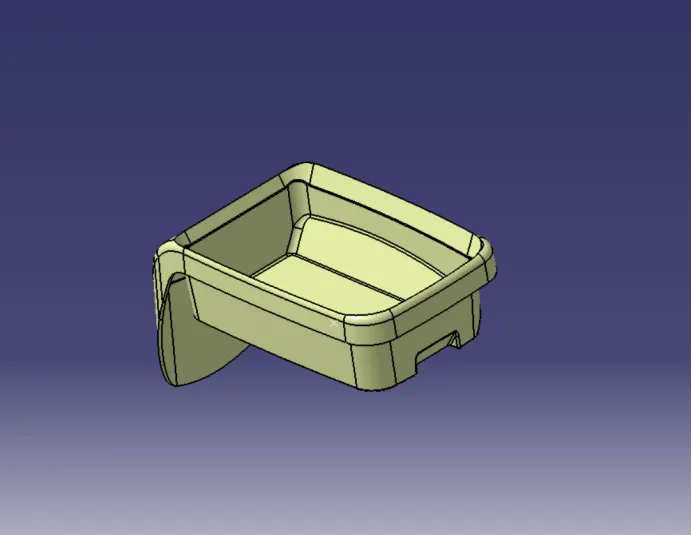
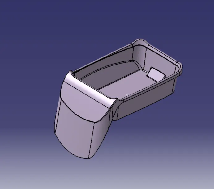
Then trim it from a Class B surface
The final output surface is shown in the below image
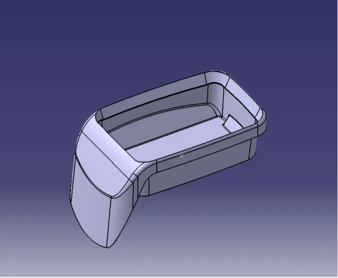
- Creating a solid body by using a closed surface :
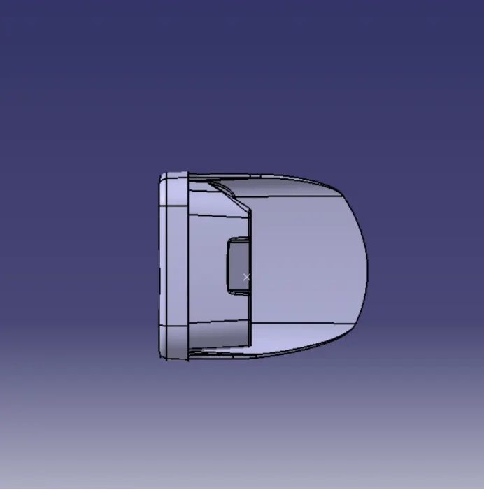
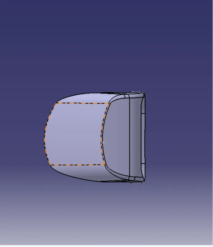
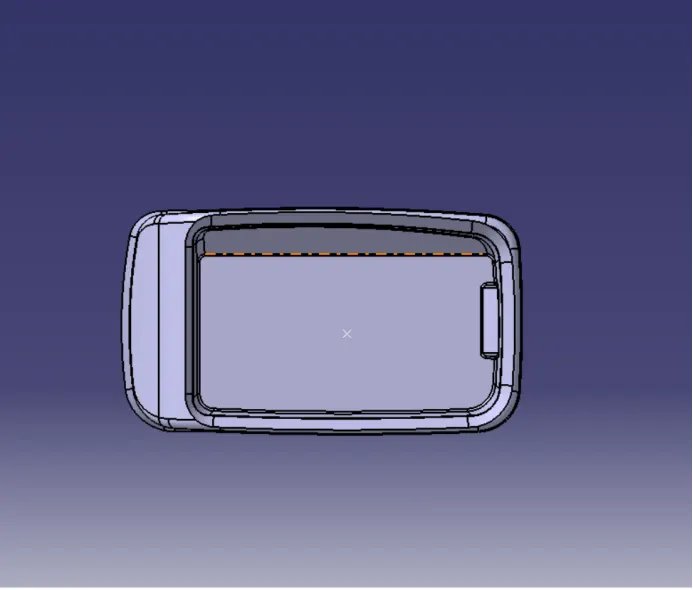
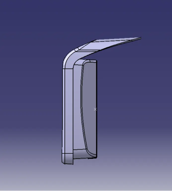
Solid-body is created by a closed surface feature in the Part Design workbench in the defined part body. This is our design output shown as given below in various orientations.
Views -

Draft Analysis -
Draft Analysis of Class A surface -
Draft Analysis of the Final Plastic Product -
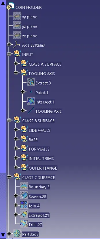
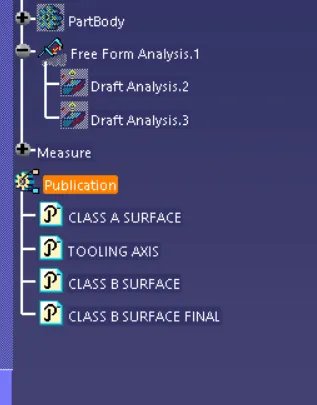
Feature Tree -