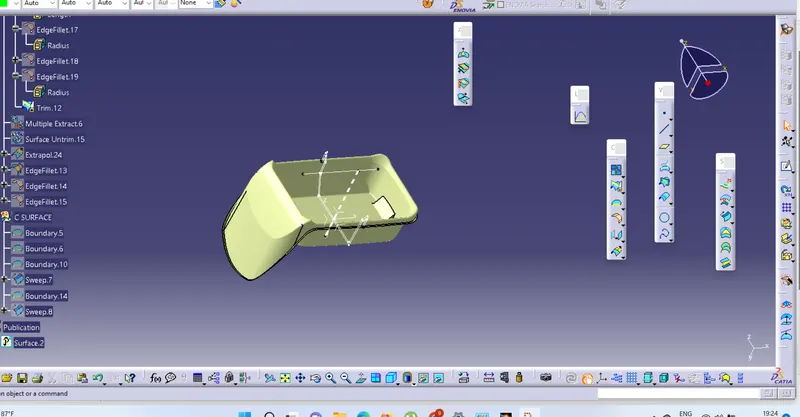
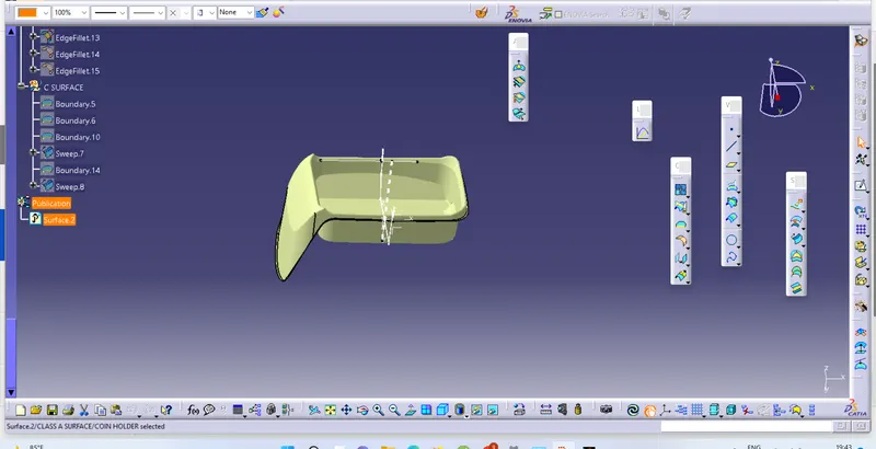
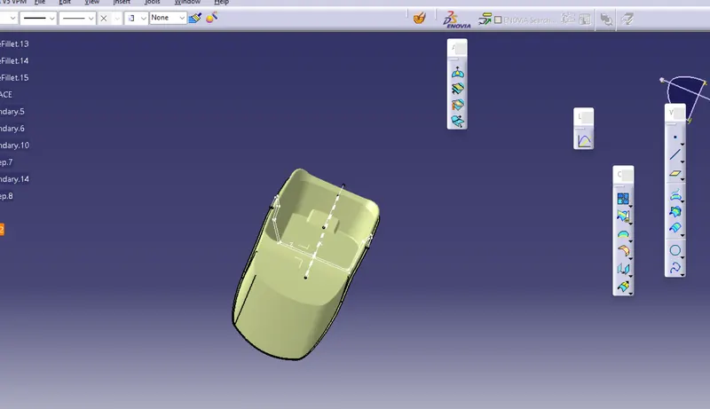
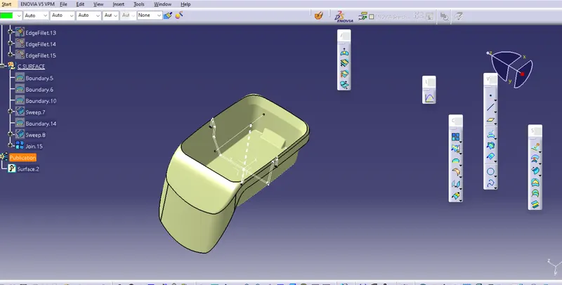
Week 8 - Challenge 3 - Coin Holder Design
BUMPER DESIGN – CHALLENGE 4
AIM
Create the Bumper Plastic component through the given Class-A surface. To begin with, the tooling axis for the given Class-A Surface should be created meeting the requirements of the draft angle and at the end perform the Draft analysis on the model.
INTRODUCTION
A bumper is a structure attached to or integrated with the front and rear ends of a motor vehicle, to absorb impact in a minor collision, ideally minimizing repair costs.
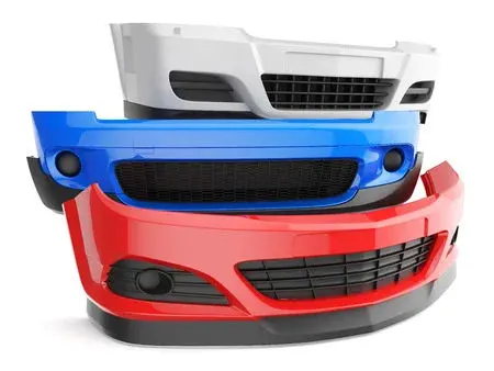
They are designed to absorb impact to the front and rear of vehicles and minimize low-speed collision damage. Today, standard passenger vehicle bumpers have a rigid reinforcing bar under the outer cover, with sections of compressible foam or plastic underneath.
A bumper is made up of four parts:
- Bumper cover.
- The bumper absorber.
- The bumper reinforcement bar.
- The bumper mounting system.
The first car bumpers were created all the way back in 1901 and consisted of metal beams attached to the front and rear of the car to protect it during a low-speed collision. Designed to protect the expensive and fragile components like the headlights, tail lights, hood, exhaust, and cooling systems, early metal bumpers were focused on sheer resilience.
Modern consumer production cars have almost completely switched over to plastic bumpers. Modern car bumpers are made from thermoplastic olefins, a blend of plastic molecules, rubber, and a reinforcing filler like carbon fiber or calcium carbonate. This blend of materials creates a scratch and impact-resistant plastic that can bond with a wide range of paints and finishes, making it ideal for vehicle bumpers.
Plastic is the preferred material for modern car bumpers for several reasons. First and foremost, plastic is much lighter and more aerodynamic than metal, which improves the car's fuel efficiency. Plastic is also easier to shape, which is useful during both the manufacturing and bumper repair process.Bumpers of most modern automobiles have been made of a combination of polycarbonate (PC) and acrylonitrile butadiene styrene (ABS) called PC/ABS.
OBJECTIVE
- To design Bumper as per automotive industry Standard.
- Create tooling axis for the given CLASS-A surface.
- Create B Class and C Class surfaces
- Create final surface model and convert it into solid body using close surface command in the part design workbench.
- Perform draft analysis for both Class-A surface and Final part body.
DESIGN METHODOLOGY
Skin data would be provided to us by the styling team to us.
Class-A surface means visible surface. It gives the aesthetic of the component which is created by the styling team and gives to the part design engineer to create the part with all engineering aspects.
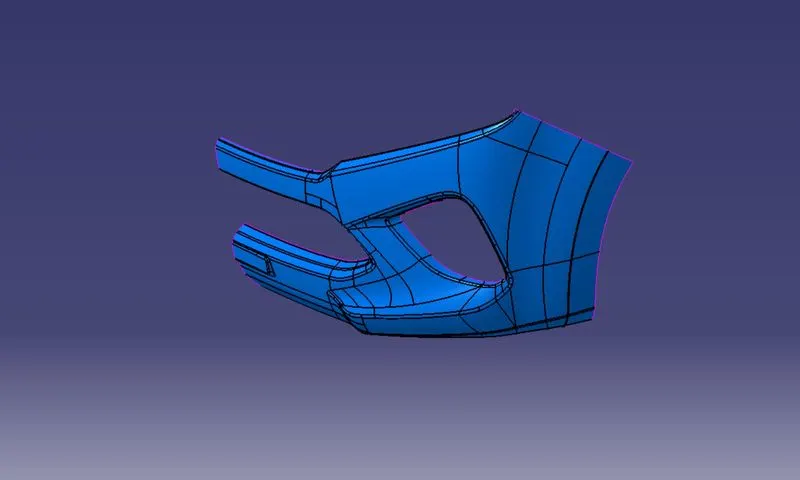
The first step is to check the continuity of the class A surface. This is to ensure that there is no gap between surfaces. If we find any then we should fix that first.
Class-A continuity check
Analyse the class A surface through visual inspection.
To make sure that the given surface has no gap in between them. We can check it also with the help of Join or boundary commands.
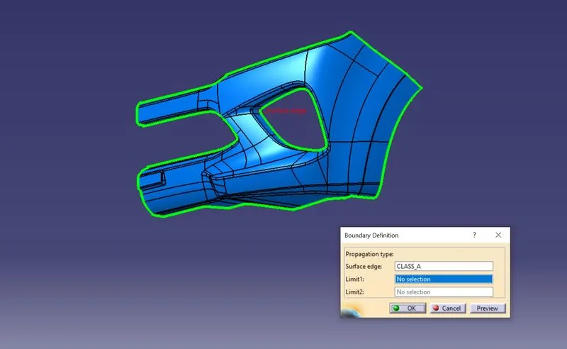
Procedure for creating the tooling axis
Tooling axis represents the opening and closing of the mold core and cavity during the manufacturing of the components. A plastic product designer should consider the best tooling direction to cutdown the cost of the component very less.
Method opted for creating tooling axis for the bumper
- Check the best tooling direction for the given surface.
- We can find out the best tooling direction by cross checking all the three axes.
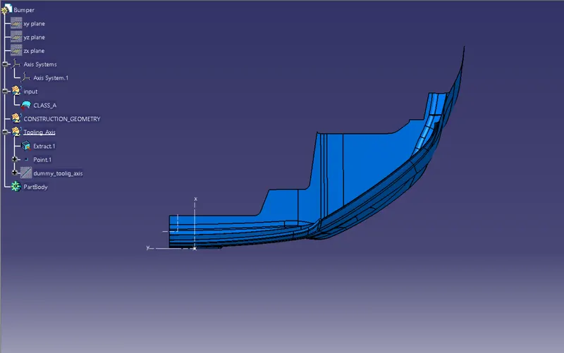
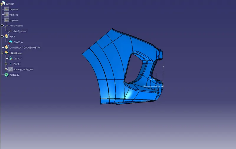
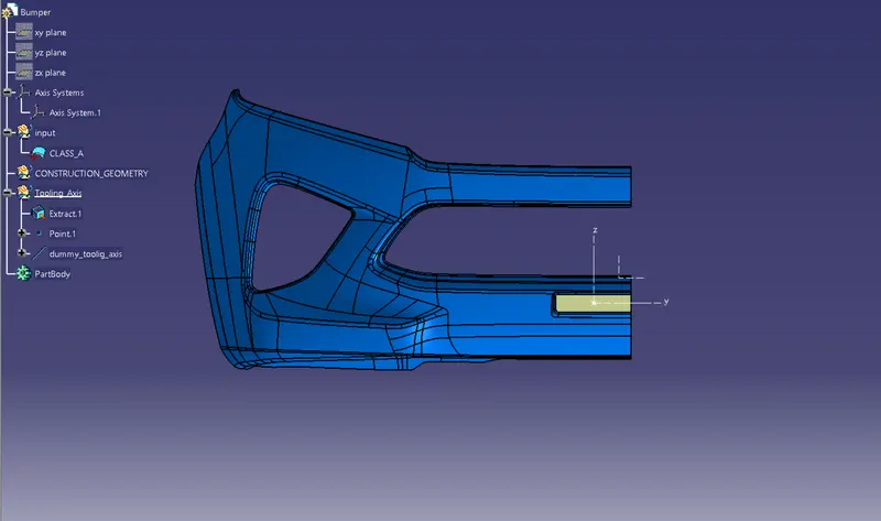
- Here we can find out that the best tooling direction for the pumper class-A surface is along x-axis direction
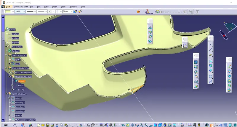
- The method I choose to create the tooling axis is first extracted a surface and create a midpoint on that surface. The introduced an axis system on that point.
- Then created a with the point and direction along x axis.
- Here both the outer flanges have 5.1-degree draft with respect to the axis created. Hence going with the axis created will not make any difficulties during the draft analysis.
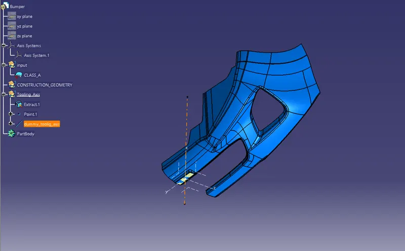
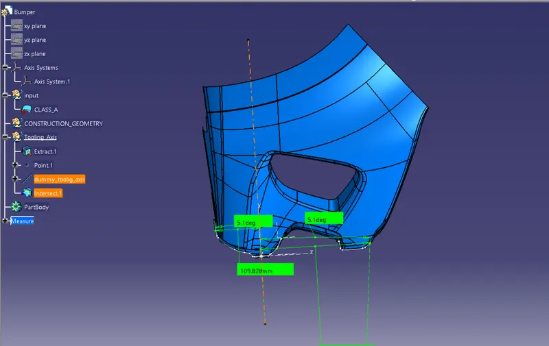
- Another method is by creating intersection along y direction. And then create lines on the walls and then create a bisecting line with the lines on the wall and point created earlier. We will get an axis which will satisfy the draft analysis requirement.
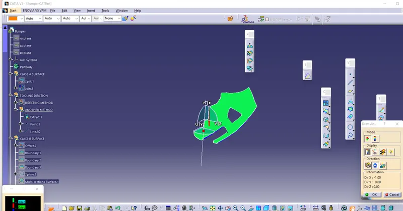
- The green colour shows the positive daft tooling direction and the given surface passes the draft analysis.
- Click on the analyses under the running point to check the draft analysis on the individual faces. It shows how much draft on specific points when we move the cursor point.
SURFACE-B CREATION
Class-B surface means thickness of a part it is not visible and is inside part. In other words, Class-B surface is a surface below a certain thickness from the class-A surface. This is the surface that contains engineering aspects of a model.
- Offset the class-A surface to 3mm inward direction.
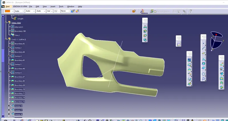
- Rework on the patches and discontinuity of the offset surfaces using the features like extract, multi-extract, sweep, multi-section surfaces, extrapolate.
- To ensure the continuity of the Class-B surfaces check the boundary command to find out the boundary.
- Hence class-B surface creation is done.
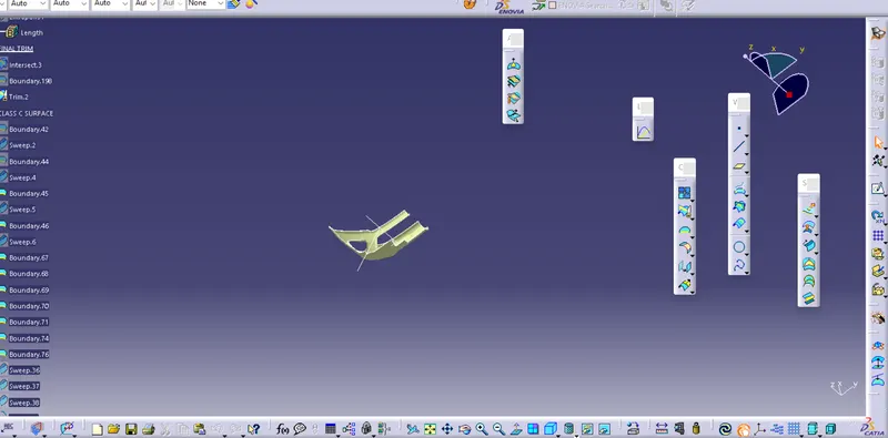
SURFACE-C Creation
Surface that joins class-A and class-B surfaces is class-C surface. Class C is often specified for interior surfaces not readily visible, surfaces that will be covered by another part when assembled.
Since it is a complex class-A surface, we cannot simply create the class-A boundary curve and sweep it at one shot. Hence, we need to create smaller curves using multi-extract command and then create sweep of 90 degree with reference to the surface option. sweeps at the midportion of the bumper should have a 93 degree vaue to pass the draft analysis.
Creating the final surface of Bumper
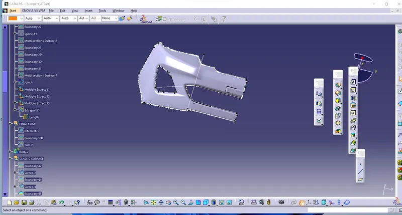
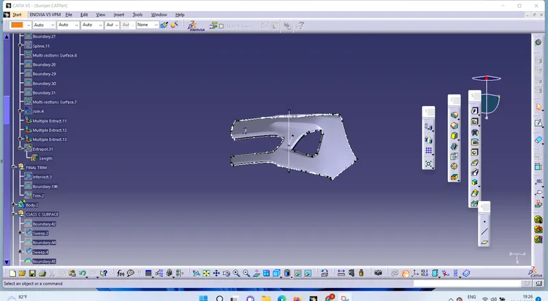
- First step is to join the CLASS-A surface with CLASS-C surface.
- Then Trim the Joined surface with CLASS-B surface to achieve the final Bumper surface.
Go to the part design work bench and using the close surface command create the base bracket solid part body:
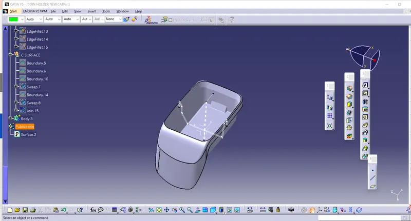
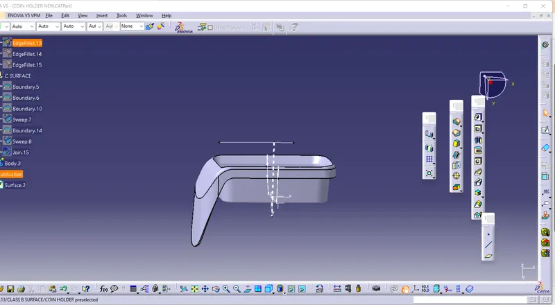
PLASTIC DESIGN OF A COIN HOLDER USING CATIA V5
OBJECTIVE
To design a coin holder used in automobiles using Catia V5 using a Class-A surface as input and performing draft analysis on the component to ensure manufacturability
INTRODUCTION
Manufacturing process: Injection Molding
Brief about the process
It is a manufacturing process used for the mass production of plastic components. It works by injecting molten material (plastic) into a mold. Under the application of heat and pressure, the material solidifies into the required shape. Once the product cools, it is ejected from the mold with the help of ejector pins.
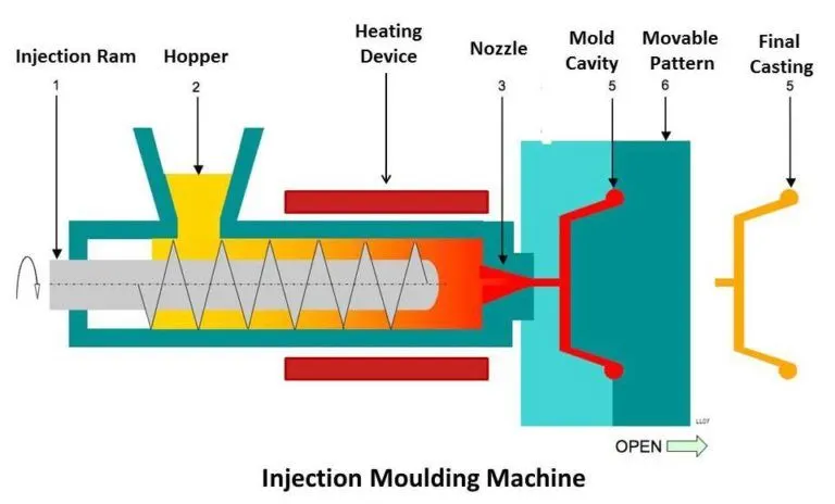
Terms in the injection molding process associated with this project
Draft
To facilitate easy removal of components from the mold, it is necessary to add a taper all along the surface with reference to the tooling direction. This taper is termed as a draft and its value ranges from 0.5 degrees to 3 degrees, with the latter being the most widely accepted norm.
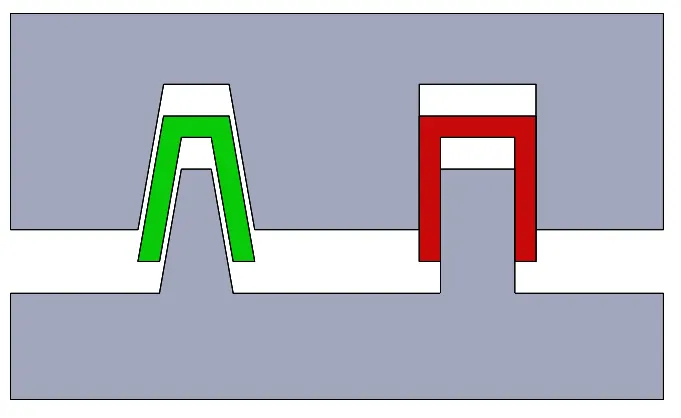
The Draft analysis command in CATIA enables to detect if the drafted part can be removed in an easy manner. This analysis is performed based on colour ranges identifying zones on the analyzed element where the deviation from the draft direction at any point, corresponds to specified values.
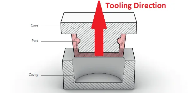
Tooling direction
The direction along which the core pulls apart from the cavity is termed as the Dyeline or the Tooling direction.
Software : CATIA V5
CATIA (an acronym of Computer Aided Three-dimensional Interactive Application) is a multi platform software suite for CAD, CAM, CAE, PLM and 3D , developed by the French company Dassault Systèmes.
The version of CATIA used for this project is V5. For the target model, the features in the part and surface workbench were extensively used.
Target Model: Coin holder used in automobiles
A coin holder is a plastic component usually found in automobile interiors especially as a part of the door arm rest.
Terms in CAD associated with this project
Class-A Surfaces
The aesthetic/free-form surface which constitutes the visible outer layer of a component can be termed as a Class-A Surface. In this project, the Class-A surface of a coin holder which is composed only of curvature continuous surfaces is used as the input for performing the draft analysis.
B and C Surfaces
The B surface forms the inner components and acts as a base for the Class-A surface. C surface connects the A and B surfaces and thereby provides a thickness for the final component
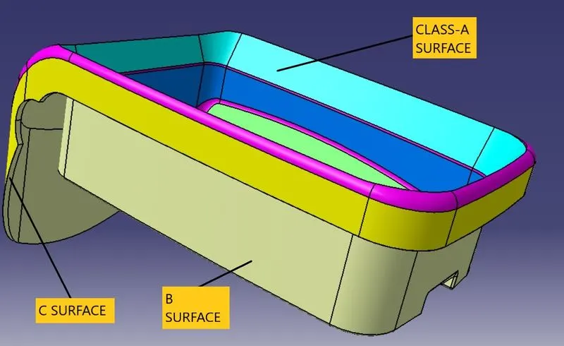
Tools in CATIA associated with this project
- Sketcher workbench: Point, Line, Intersect 3-D elements
- Part workbench: Close surface
- Surface workbench: Boundary, Extract, Multiple extract, Untrim, Extrapolate, Offset, Trim, Join, Edge fillet
Methodology in CATIA associated with this project
Bisecting line method
Since draft is measured with reference to a tooling axis, the first step after importing the model into CATIA was the creation of a tooling axis. To incorporate for tool clearances due to the presence of tapered surfaces in the part, the bisecting line method was used to create the tooling axis.
After converting the surface into a 2D profile using the Intersection command from the surface workbench, two inclined lines were created using the endpoints of the 2D curves which represented the tapered faces. Using a bisecting line type, a third line was created along the centre point which signified the coincidence of the tapered faces. This line was the required tooling axis for this component.
NOTE: This project did not have features which needed a titled tooling axis and hence the tooling axis was created using a bottom face extract and creating a line through the centre point.
Draft Analysis
The draft analysis command in CATIA helps to detect whether the drafts provided in the model will facilitate easy removal of the component during manufacture.
This analysis is performed based on colour ranges identifying zones on the analyzed element where the deviation from the draft at any point, corresponds to specified values.
- When the draft angle value of the surface is equal or smaller than a graduated value, the color below the graduated value is applied
- When the draft angle value of the surface is greater than the greatest graduated value, the color above this graduated value is applied
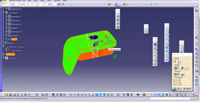
In this project, the required draft for all surfaces were chosen as 3 degrees and hence the quick mode option in draft analysis was chosen which incorporated two different colours for two input values.
B and C surface creation
The B surface was created by offsetting the Class-A surface and then extrapolating it to accommodate the entire area of the Class-A surface.
The C surface provided the thickness and acted as the joining surface between Class A and B surfaces.
The Class A and C surfaces were made into a single surface using the Join command in the surface workbench. This was then trimmed (Trim tool) using the B surface to create the final component. The model was then converted into a solid using the Close Surface command.