Week 8 Challenge
Aim:
To develop a mathematical model of Ultracapacitor.
Objective:
To Output the ultracapacitor SOC , voltage and current using the parameters defined in UC_data.mat file. Input is the Power demand of UltraCapaciotor (PUC) which probably comes from the energy management system (EMS).
Theory:
- UC is a high power and low energy device i.e., it can discharge quickly to accommodate the high power demand from the vehicle.
- In UC unlike in other energy storage systems like battery there is no chemical reaction take place inside the cell. Charge is accumulated on the electrode plates when charged and same charge is removed from electrode while discharging.
- In UC, State of Charge (SOC) can be calculated by calculating the UC_Voltage as they both are directly proportional. Voltage is directly proportional to the amount of charge accumulated inturn charge and current current proportional while current is proportional to SOC.
- SOC, Voltage, current values keep on changing while driving. So equations are used to develop the model.
Mathematical model:
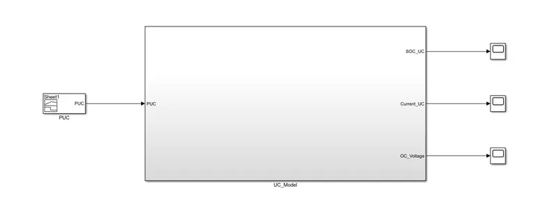
UC_Model:
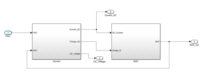
Current: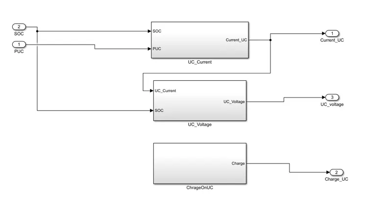
UC_Current: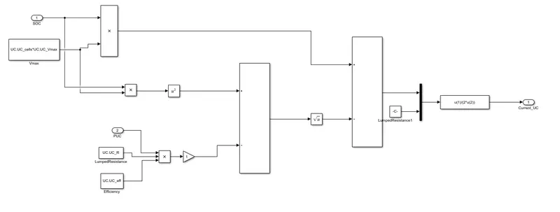
The above model represents the calculation of UC_Current which is given by below equation
`I=(SOC**Vmax-sqrt(((SOC**Vmax)^2)-4**R**PUC*eta))/(2**R)`
All the above values are loaded in the base workspace by running the UC_Data.mat file.
UC_Voltage: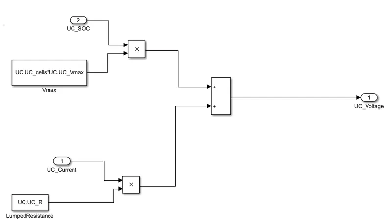
The above model is for calculating the UC_Voltage, the equation is as follows
`V=(SOC**Vmax)/(I**R)`
Where I is the UC_Current and R is the lumped resistance.
Chargeon UC: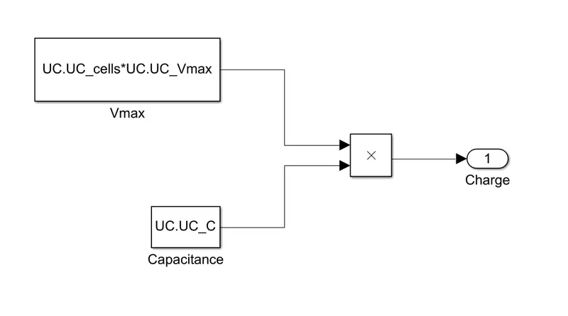
Above model is for calculation of charge on UC, represented as
`Q=Vmax**C`
SOC: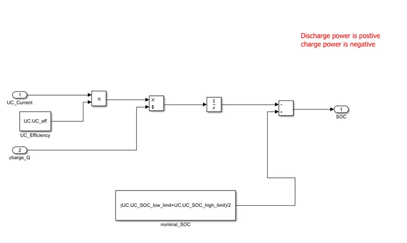
`SOC=int(I**eta)/Q**dt`
Note:
Intially the SOC of UC assumed to be nominal capacitance which is the average of high and low SOC of UC. Nominal SOC used to accommodate both charging and discharge initially. If initial SOC is high limit of SOC then if any braking occurs but the regen power cannot be harnessed bu UC since it is already full (higher limit) similarly if initial SOC= lower limit then there wont be any power for acceleration intially. So it is better to keep initial SOC as the average of high and lower SOC.
Results:
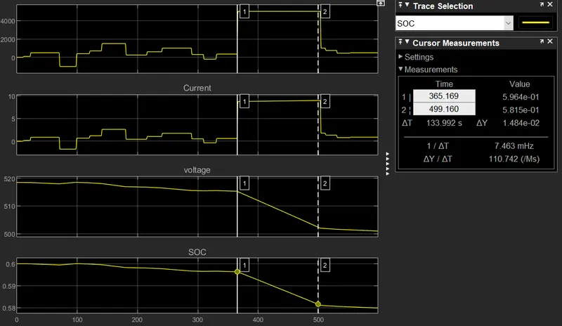
- UC_Current follows the power demand (PUC) Where as SOC and UC_Voltage plots are same which shows thay they both are proportional as discussed earlier.
- PUC comes from EMS where optimization algorithms decide the value of PUC.
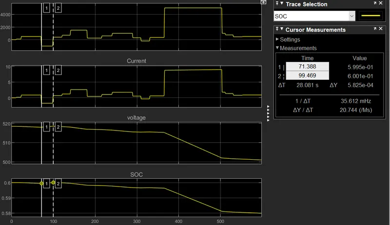
- In above plot when PUC is negative which implies that there is scope for regeneration the value of SOC increases as shown in above figure with the cursors.
- When power demand is positive which indicates discharging, the value of SOC decreases as shown in below plots.