Week - 4
1. state diagram:
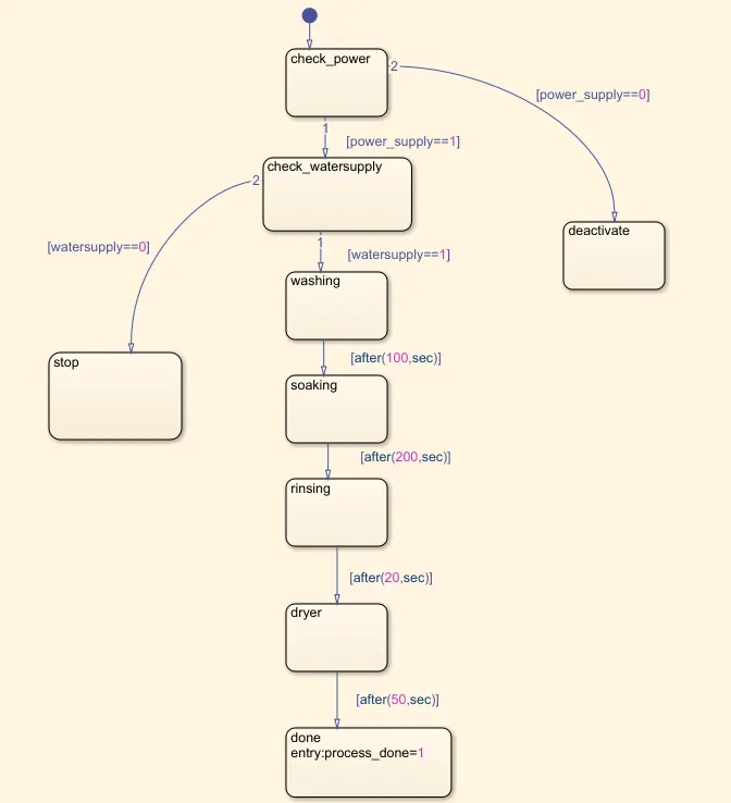
- Inputs to the state flow are power supply and waterflow
- If power supply is not present the system is deactivated, this is done by giving condtions across the arrows connecting the blocks.
- If power suplly is present the check is done for water supply, if watersupply is present then washing is done followed by soaking, rinsing, drying by providing appropriate delays as per the given question between the states and then the process of washing is done, if watersuplly is not present the process is stopped.
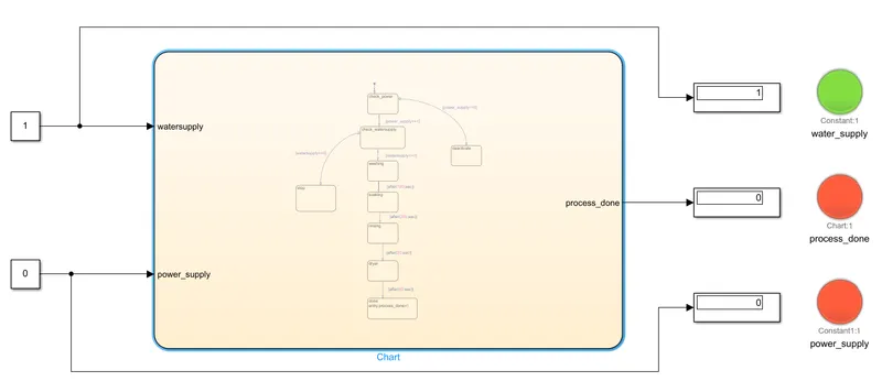
- LED are indicated for power supply, watersupply and the process done. If power and water supply is present it is indicated by GREEN or else by RED colour. similarly if the process is done it is indicated by GREEN if not done indicated by RED.
2.
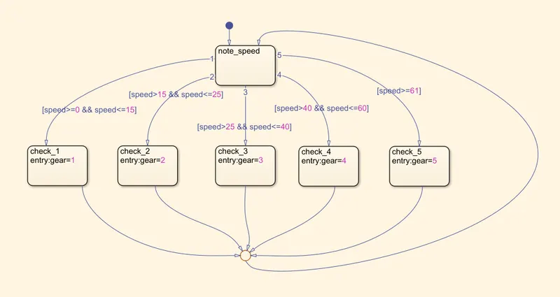
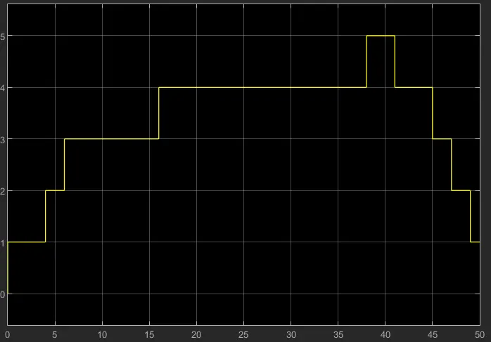
- Speed is taken as the input and gear number as the output.
- The gear number for different speed ranges is given by the different states in the state diagram by providing the conditions across the arrows.
- The output of each gear is connected to the first state through a junction so that for every continous change in speed the gear number also changes continously.
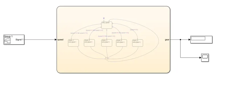
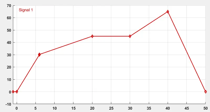
input: input signal is from signal builder.
output:
note: the constants or varibles used in the state flow are configured as input or output by using the system pan in the simulation tool bar.