Week 8 Challenge
AIM & INTRODUCTION:
To calculate the centrifugal load for the following load data.
CENTRIFUGAL FORCE:
The moving of a vehicle in a curve produces an outward pushing force from the bridge which exerts loads on the structural elements of the bridge called as the Centrifugal Force.
GIVEN DATA:
- The span of the bridge is 12 m.
- Width of carriage way is 7 m.
- The bridge is subjected to a live load of Class 70R tracked vehicle.
- The design speed of the vehicles is 75 km/hr.
- The radius of curvature in the bridge is 3 m.
PROCEDURE:
Calculation of Centrifugal Force:
Design Speed,V=75KM/hr
Radius of Curvature,R=3m
Live Load,W=70KN
Centrifugal Force=W*V^2/127R
=70*(75)^2/127*3
Centrifugal Force =1033KN.
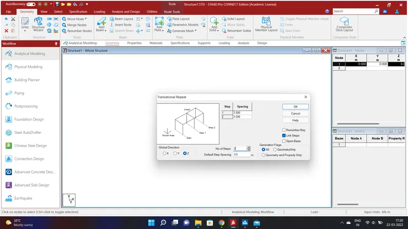
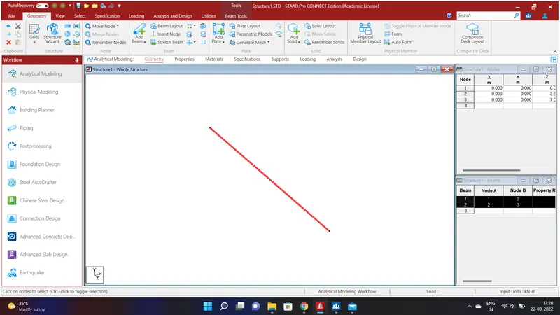
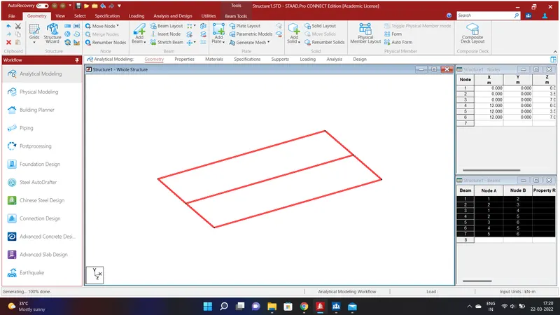
Create a node by assigning the values of X=0;Y=0;Z=0. Selecting the node using node cursor in the select option go to Geometry option and select Translational Repeat in Global Z Direction and assign the values of No.of Steps=2 and Default Step Spacing=3.5m and click Link Steps and click OK.We have created a beam of width 7m. Again go to Geometry option and select Translational Repeat in Global X Direction and assign the values of No.of Steps=1 and Default Step Spacing=12m and click Link Steps and click OK.We have created a beam of width 7m and Length 12m.
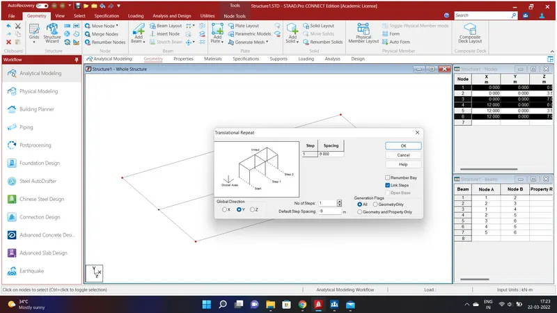
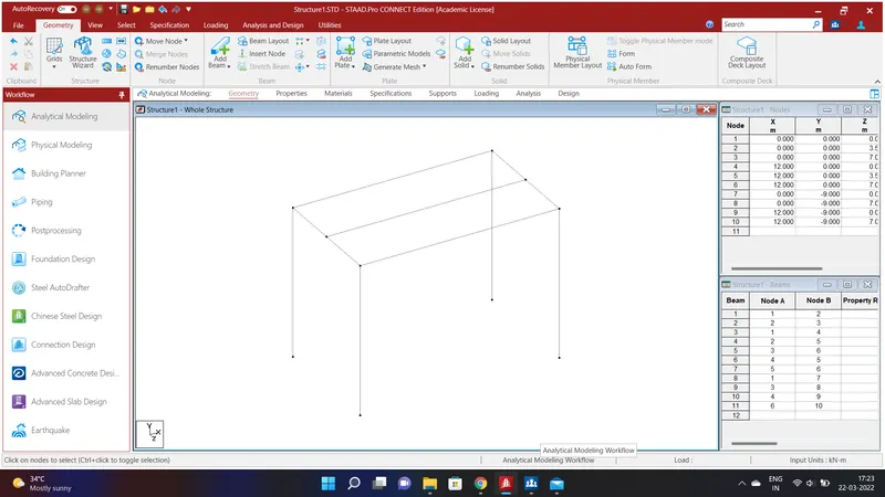
Again select the corner nodes using node cursor in the select option and go to Geometry option and select Translational Repeat in Global Y Direction and assign the values of No.of Steps=1 and Default Step Spacing=-9m and click Link Steps and click OK. We will have created Piers of Height 9m.
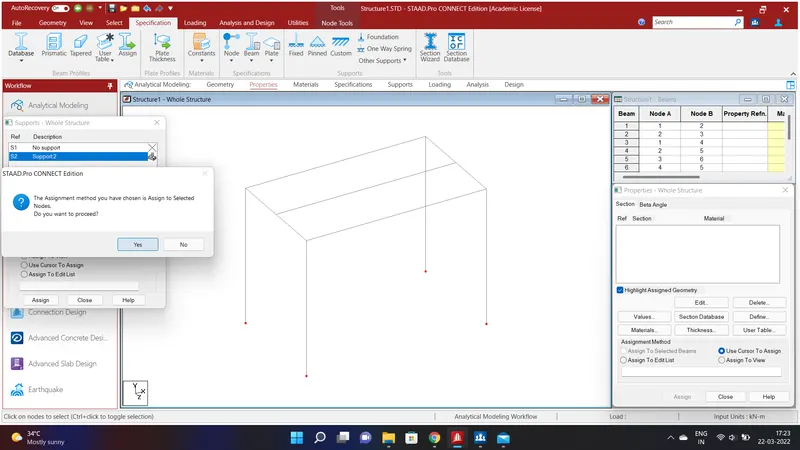
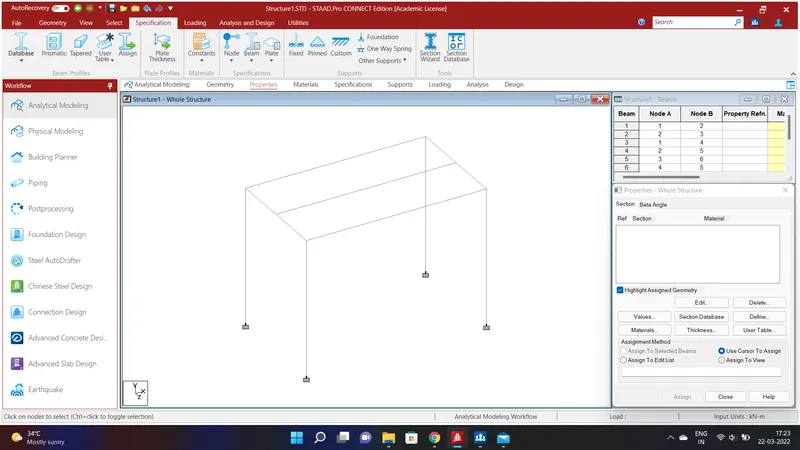
Select the bottom pier nodes using node cursor in the select option and go to Specification Option and select Fixed and click Add and select Support 2 and Assign to Selected Beams and Assign and click YES. We will have created a Fixed Support.
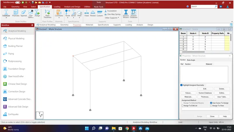
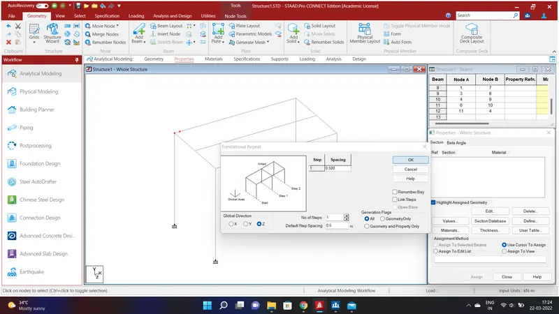
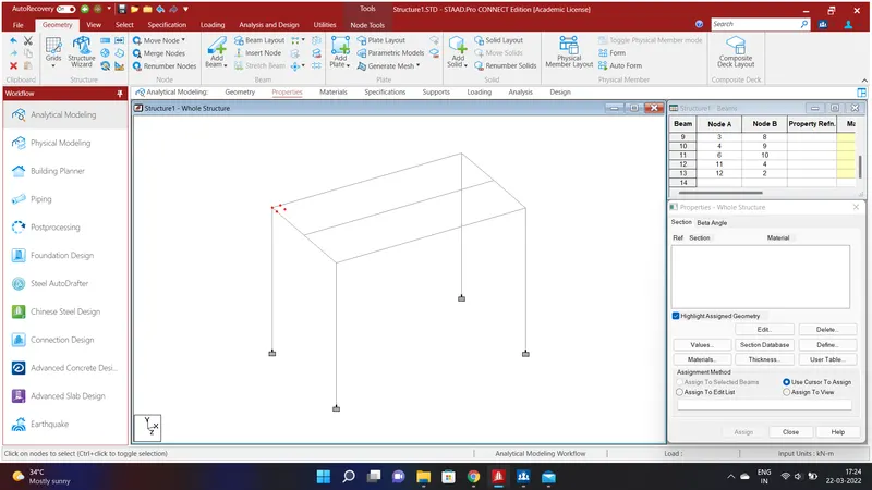
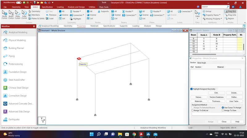
We have to create a Deck Slab. To do so go to node cursor in the select the node and go to Geometry option and select Translational Repeat in Global X Direction and assign the values of No.of Steps=1 and Default Step Spacing=0.5m and click OK.Again go to Geometry option and select Translational Repeat in Global Z Direction and assign the values of No.of Steps=1 and Default Step Spacing=0.5m and click OK.In geometry option select Add Plate and connect the nodes and go to select option and click plate cursor and click the plate.
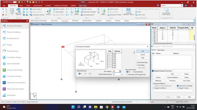
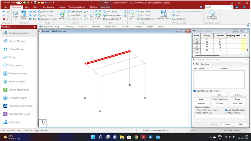
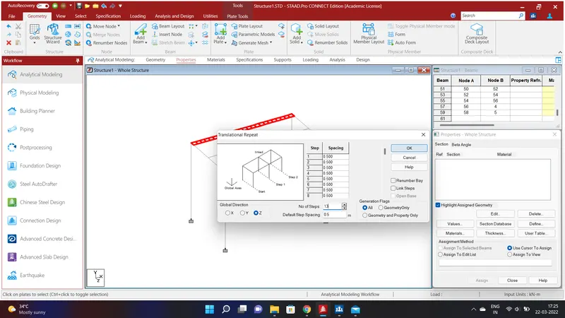
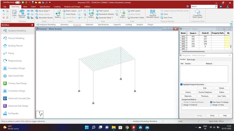
Select the plate and go to Geometry option and select Translational Repeat in Global X Direction and assign the values of No.of Steps=23 and Default Step Spacing=0.5m and click OK.Again select all the plate and go to Geometry option and select Translational Repeat in Global Z Direction and assign the values of No.of Steps=13 and Default Step Spacing=0.5m and click OK.We have created Deckslab throughtout the bridge.
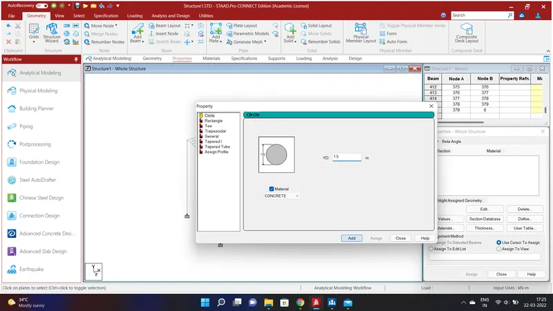
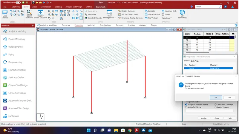
We have to assign properties to the Structure. To do that go to Specification Option and select the Prismatic Option and assign the value of pier as 1.5m using Concrete Materials and click ADD. Now select all the piers and click Assign to Selected Beams and Assign and click Yes. A pier size of 1.5m dia is assigned to all the piers.
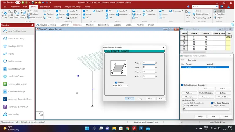
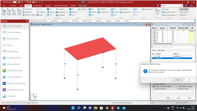
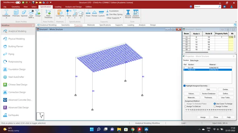
We shall assign properties to the Deck Slab. To do that go to Specification Option and select the Plate Thickness Option and assign the value of Deck Slab as Node 1=0.5m;Node 2=0.5m;Node 3=0.5m;Node 4=0.5m using Concrete Materials and click ADD. Now select all the plates and click Assign to Selected Plates and Assign and click Yes. A Plate Thickness of 0.5m is assigned to all the Deck Slab.
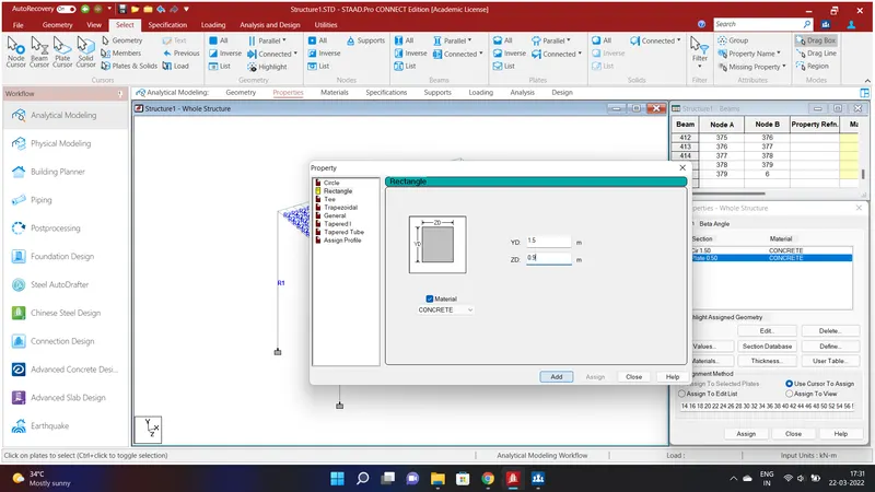
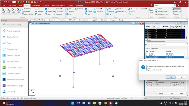
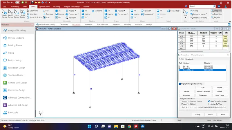
We have to as assign properties to the Girders. To do that go to Specification Option and select the Prismatic Option and assign the value of Girder as YD=1.5m;ZD=0.9m using Concrete Materials and click ADD.Now select all the Girders and click Assign to Selected Beams and Assign and click Yes. We shall have assigned properties to the Structure.
RESULT:
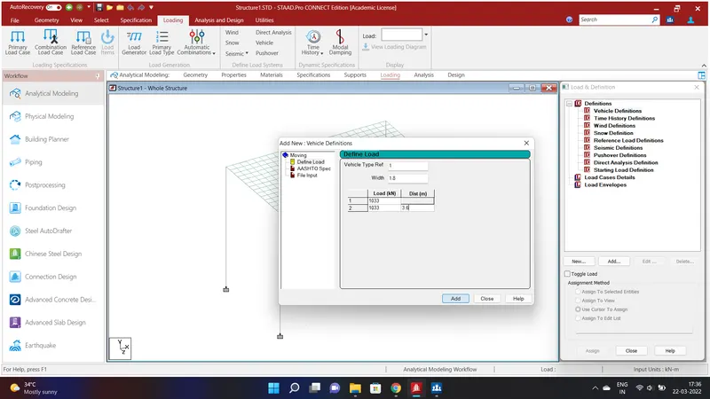
After assigining properties to the structure we shall give the Centrifugal force to the moving Vehicle . To do that go to Loading Option and select Definitions and go to Vehicle Definition and click Add. Give the Width of the vehicle as 1.8 and apply the load calculated above and click Add .
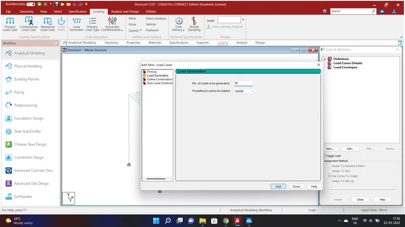
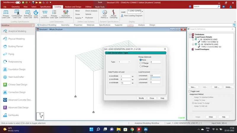
We will apply the Centrifual Force on the Bridge Structure. Go to Load Case Details and click Add and go to Load Generation and give No. of Load to be Generated as 28 and click Add.Select the Generated Load and click Add and give coordinates as follows X Coordinate=1;Y Coordinate=0;Z Coordinate=1.5 and the Increment of X=0.5 and click Add.
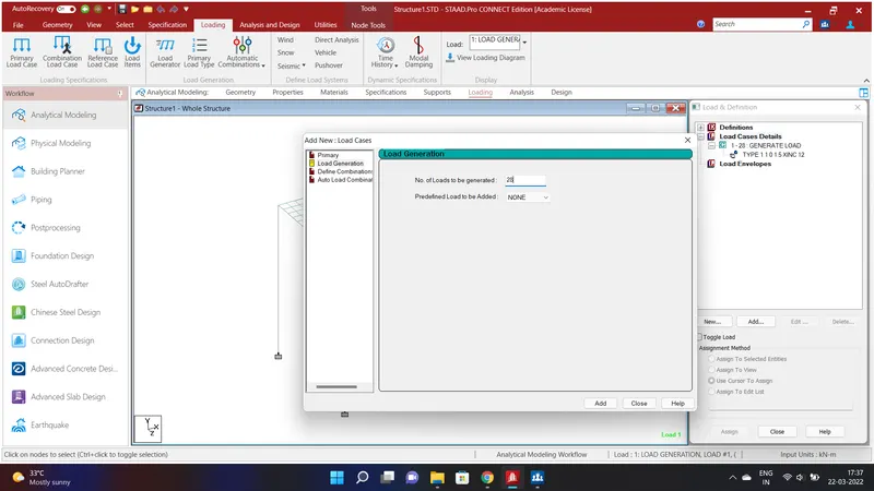
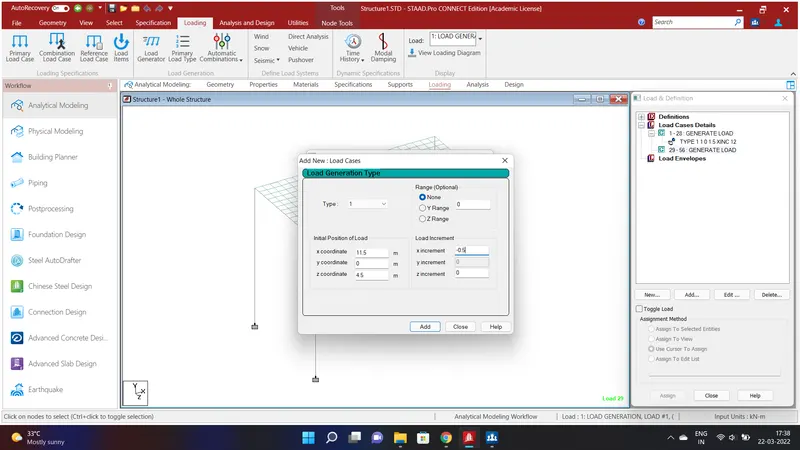
Again go to Load Case Details and click Add and go to Load Generation and give No. of Load to be Generated as 28 and click Add.Select the Generated Load and click Add and give coordinates as follows X Coordinate=11.5;Y Coordinate=0;Z Coordinate=4.5 and the Increment of X=-0.5 and click Add.After assigning the loads we shall analysis and design.
REPORT:
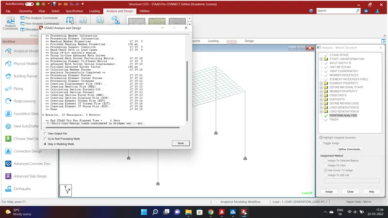
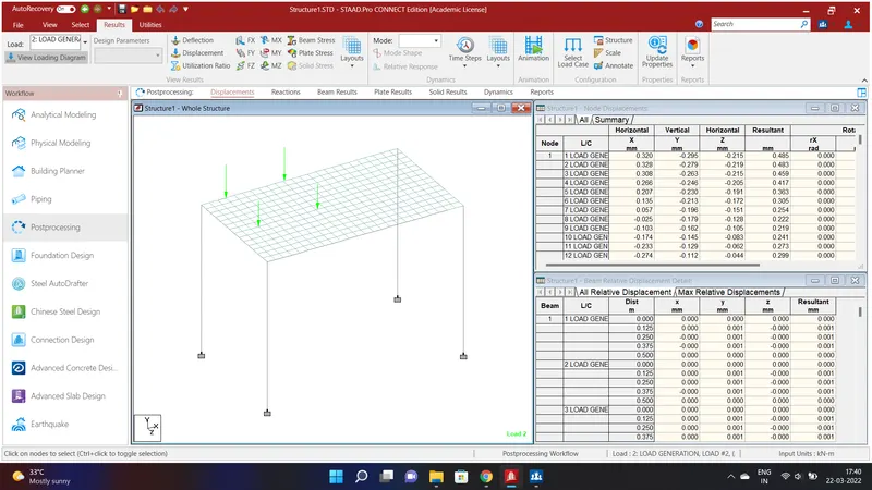
After loading go to Analysis and Design option and select Analysis Command and click Add. Go to Run analysis and run the analysis. After running the analysis go to Post Processing Mode and click ok. Select the View loading Diagram and we can see the loads moving on the Bridge.
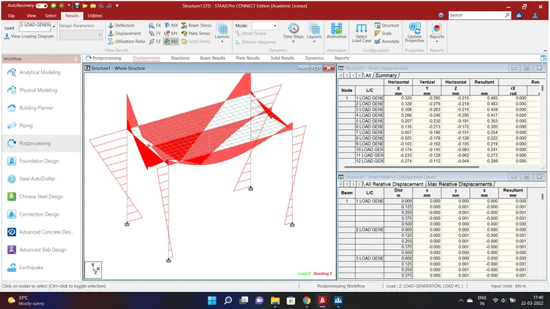
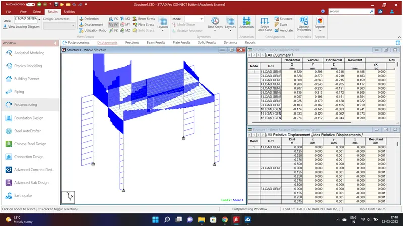
Bending moment at Z and Shear Force at Y is shown above.
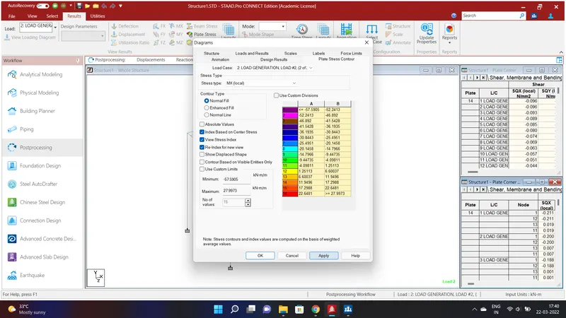
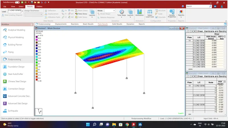
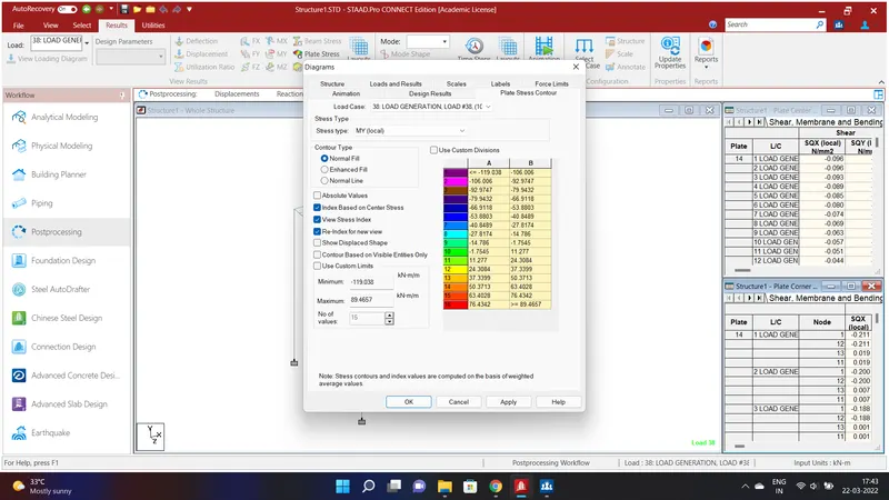
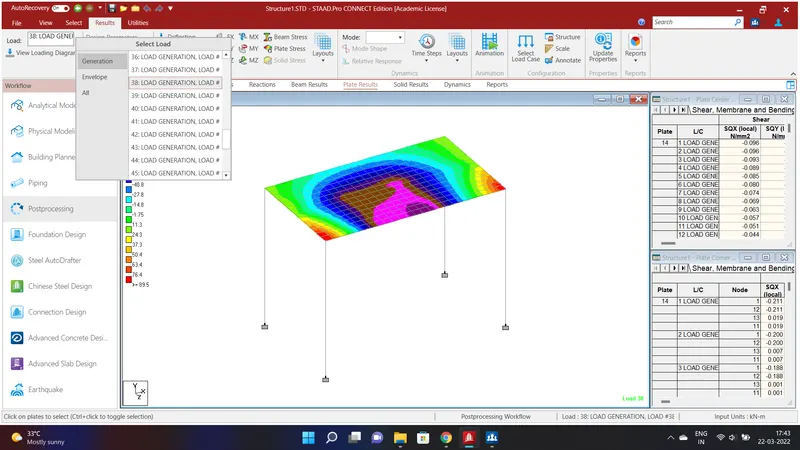
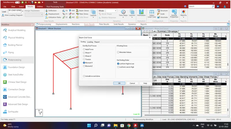
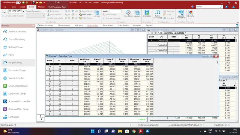
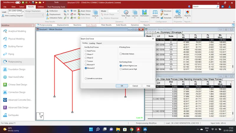
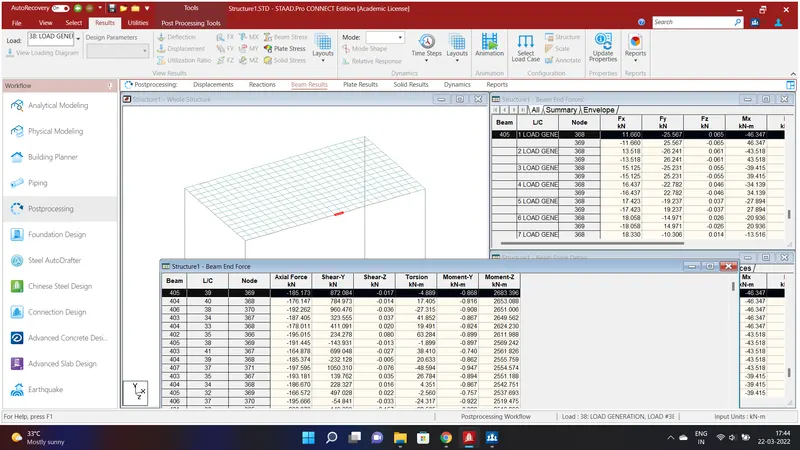
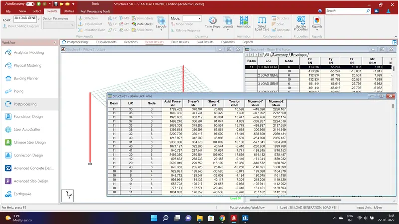
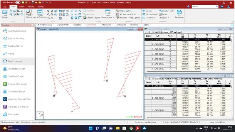
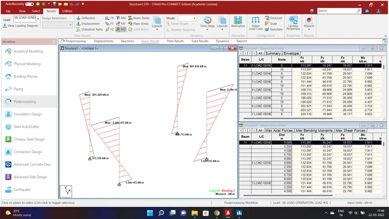
We have calculated and taken the Report for Plates.
* Moment at X-MX(Local)
* Moment at Y-MY(Local)
For Beams Moment at X and Moment at Y are obtained in the Report.