Week 8 - Challenge 2 - Switch Bezel Design
Solid Model
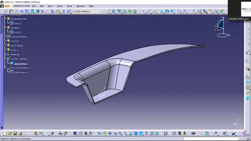
Draft analysis of final plastic product
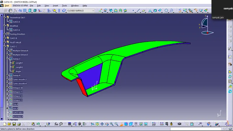
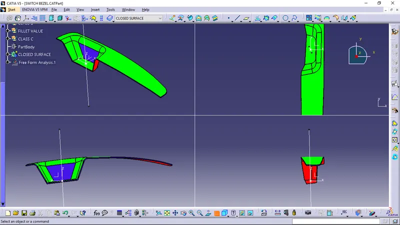
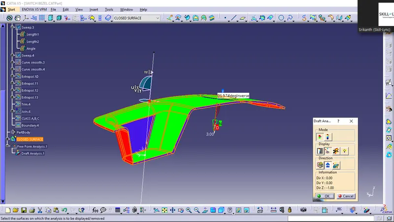
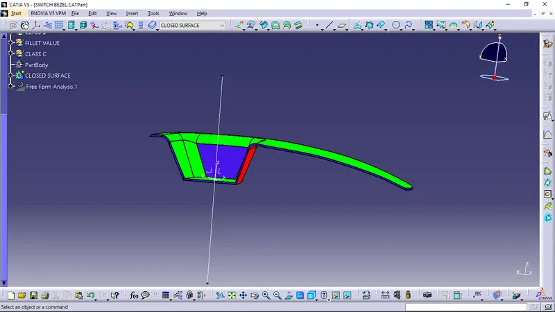
To be able to do draft analysis first we nned to have appropriate tooling axis, the position of tooling axis determines the success of the design and its ejectibility.
Here, we have created the axis by bisecting method.
The axis shown in image is tooling axis.
To be able to create the final axis we have created two geometries one of which is -
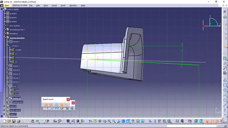
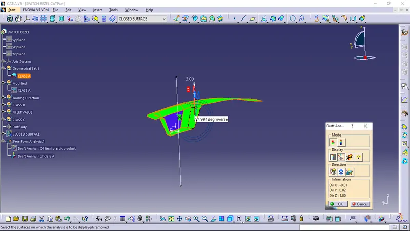
1] First thing which we did is to have a center point which will be convenient for further analysis, here We have taken the center point og the circ le which can be seen in the picture.
2] Then, in catia we had by using intersection we created horizontal line on the profile.
3] Next step is to draw line on this profile on both the tapered section by selecting two points.
4] Here, then the tooling axis is created by choosing bysecting, selecting two line and selecting middle center point created.
5] Due to the geometry of the body we took another axis at a 3 degree angle with respect to
This is the way Tooling axis is created.
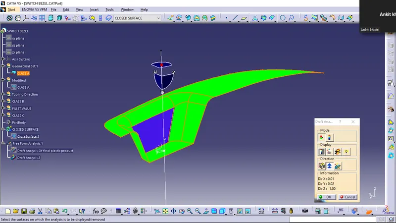
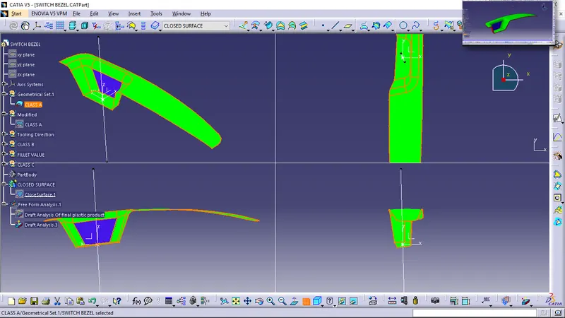
As we can see the draft analysis 1 shows complete green colour.
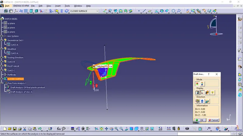
Here colours show the ejectability by stating whether the draft angle is right or wrong.
Green = Draft value above 3 deg
Red = Below 0deg
Blue = 0-3 deg
Draft Analysis 1
As we know first analysis is performed on the class A surface which is green and blue , it shows the ejectability by the analysis.
Draft Analysis 2
But the section analysis where class A, class B, class C all these surfaces are involved .
In these analysis we can see blue and red colour section is also there.
It shows the the position of tooling axis with respect to the class B and Class C surface is not appropriate.
Here we need to change some things in the design.