Week 8 - Challenge 2 - Switch Bezel Design
OBJECTIVE
To create base bracket using given class A
To create tooling axis
To perform draft analysis
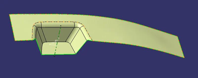
CLASS A SURFACE:
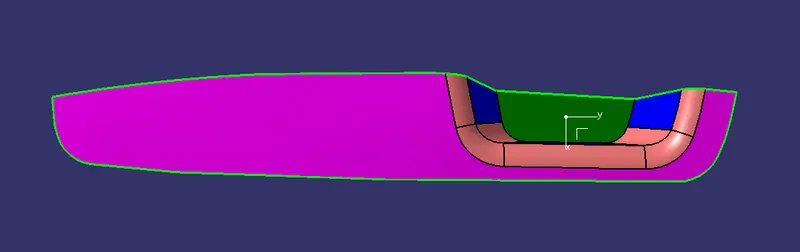
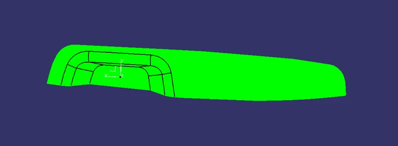
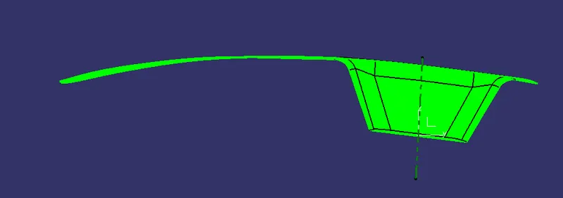
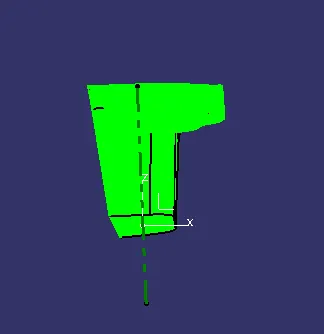
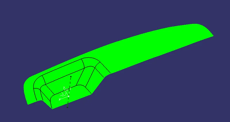
The above image represents the class A surface given as input.
GENERATING TOOLING AXIS
1.First the connectivity of the class A surface is checked by using boundardy option on the surface.
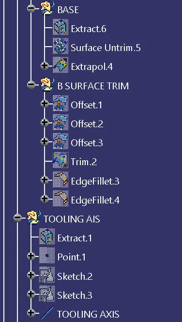
2. Extracting the base surface and creating a point on the surface and creating a axis system.
3. The intersion option is used along YZ plane and the drawing direction is assumed to be along the interstion of the curves.
and creating two lines along the surface and using bisecting line option tooling direction along yz plane is created.
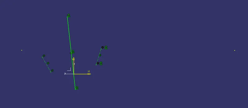
4. the along zx plane
the intersection along the surface is taken for zx plane and a line over the intersection wall surface is created.
another line with start point as centre point is used and fixed for a angle of 6 degree.
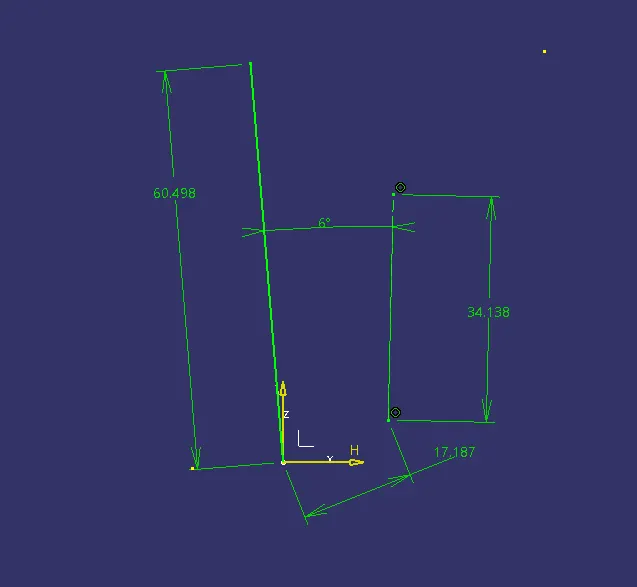
the tooling direction along zx plane is created.
5. By bisecting the zy tooling axis and zx axis direction . Main tooling axis created.
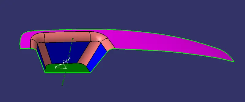
CLASS B SURFACE CREATION:
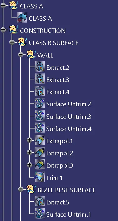
1. The side walls,bottom surface, bezel rest surfaces are extracted.
2. untrimmed individually.
3. they are offsetted for 2.5mm as the given thickenss is 2.5mm.
4. extrapolated for appropriate distance so that they can be trimmed.
5. all the extrapolated surfaces are trimmed, fillets are applied and the final CLASS B SURFACES IS OBTAINED.
CLASS C SURFACE:
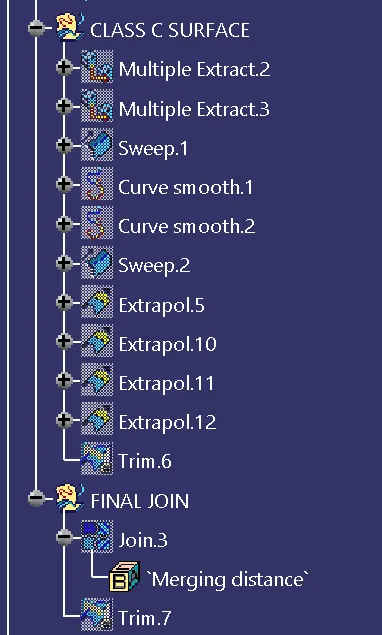
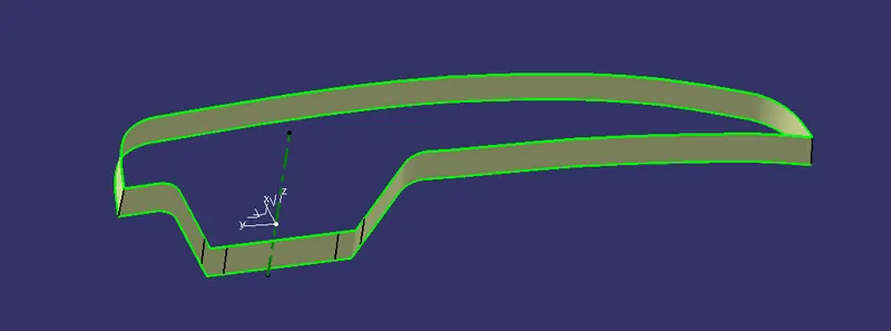
1. The edges of the class A surfaces are extracted as two sets and are smoothened using smooth curve option.
2. They are swept along the tooling direction with 3 degree draft along outward direction.
3. they are extrapolated and trimmed off to make as a single CLASS C surface.
FINAL SURFACE CREATION
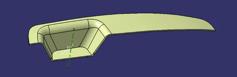
1. The CLASS A and CLASS C surfaces are joined together.
2. the joined surface is trimmed with CLASS B surface and the final closed surface is obtained.
To check for the correctness of the final surface boundary option is used and if it is not created. the created surface is good to be thickened.
CLOSED SURFACE CREATION:
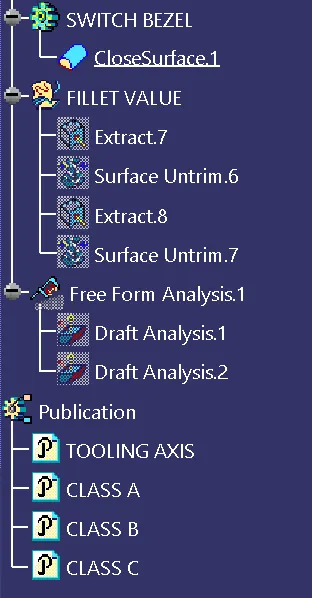
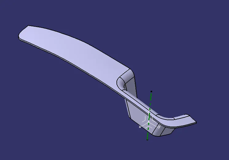
1. By going to part design and using closed surface option. the Thickened component is created.
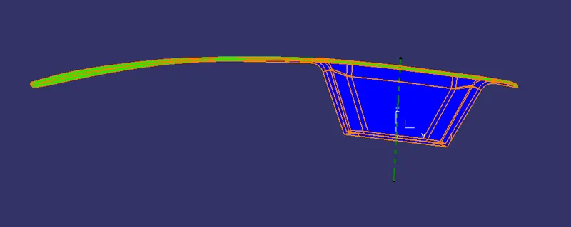
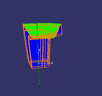
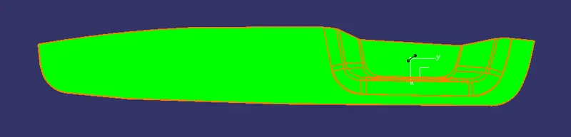
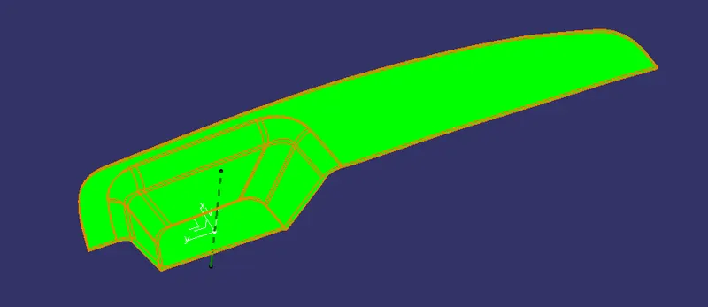
DRAFT ANALYSIS:
FOR CLASS A SURFACE:
TOP:
FRONT:
LEFT:
ISO:
THICKENED COMPONENT:
FRONT:
LEFT:
TOP:
ISO:
TREE STRUCTURE: