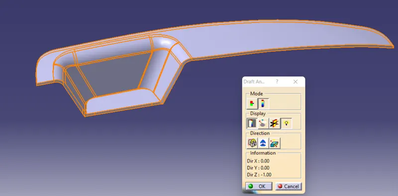
Week 8 - Challenge 2 - Switch Bezel Design
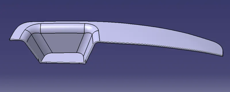
AIM: To create the Switch Bezel Plastic component through the given Class-A surface. To begin with, the tooling axis for the
given Class-A Surface should be created meeting the requirements of the draft angle and at the end perform the Draft
analysis on the model.
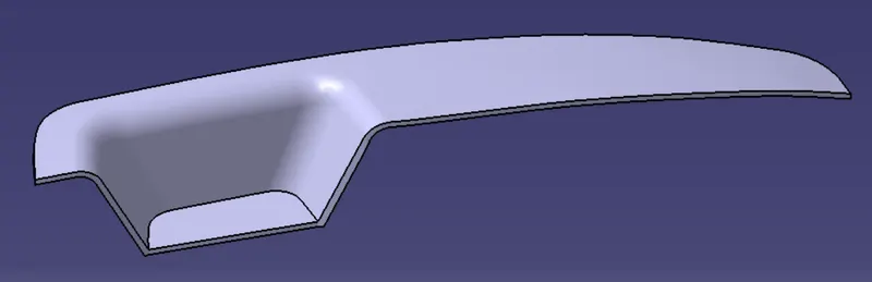
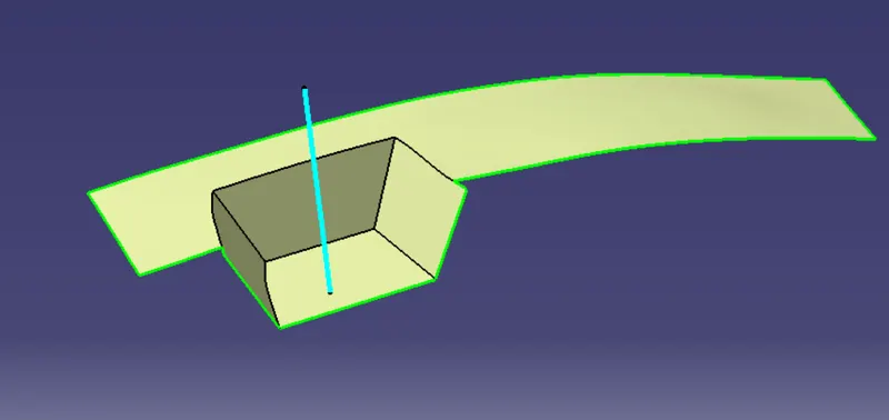
Given class A surface:
The below image shows that the Class – A surface is clean and no irregularities present, so let's move on to the next step.
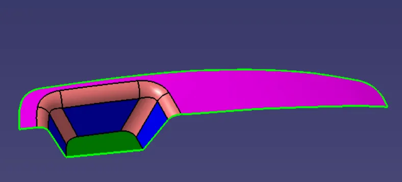
Surface-A
Introduction:
Class A surface: the class-A surface is used in the automotive design industry. it describes the final production surface data for the aesthetic parts.
Class B surface: the class-B surface is the second surface that has a certain thickness from the class-A surface. this surface contains engineering aspects of a model. These must be smooth and "error-free" as well but are not held to the standards that class A surfaces are.
Class C surface: The Class C finish allows more imperfections than Class A or B. Class C is often specified for interior surfaces not readily visible, surfaces that will be covered by another part when assembled, or surfaces.
Design consideration:
- Class – A surface should be aesthetically smooth and good.
- Class – B surface should have all the supporting features like ribs.
- Parting Line should coincide with the B surface since flashing couldn’t affect the aesthetic of Class – A.
- Class – C surface should also pass the draft analysis.
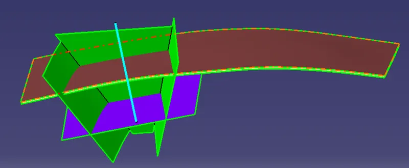
The above image is having
- Bezel rest surface
- Base
- 3-suppourting walls
Tooling direction:
- Considering the Ejection from the cavity of the mould after manufacturing the interior trim (switch bezel) must have the nominal 3-degree draft angle.
- Hence the tooling direction is created by considering the above factor and bisecting method is used.
- The base surface of the class – A was extracted and a point at the centre is created and an axis system was inserted to the point with the current feature is disabled.
- Then, using project intersection along yz plane is created and the two inclined lines were drawn inside the positioned sketch.
- Then bisecting lines with the two inclined lines were drawn.
- Now the same procedure is done along the xz plane but on one side we don’t have inclined lines so the centre point is used to extrude a line along the z-direction and gave a measurement of 5 degrees.
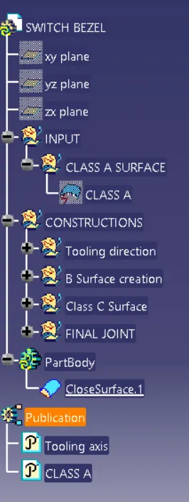
With these two lines from sketches 1 and 2, the bisecting line is crated and published as Tooling Axis.
Surface-B
Final product
Final tree