Week 8 - Challenge 2 - Switch Bezel Design
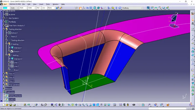
Creation of tooling axis:
- Create a point in the surface of the cavity.
- Create a intersection line of the surface with the two plane which are perpendicluar to each other.
- Create a bisecting line for each of the intersection lines from the point.
- Now the final bisected line can be considered as a tooling axis for the switch bazel surface.
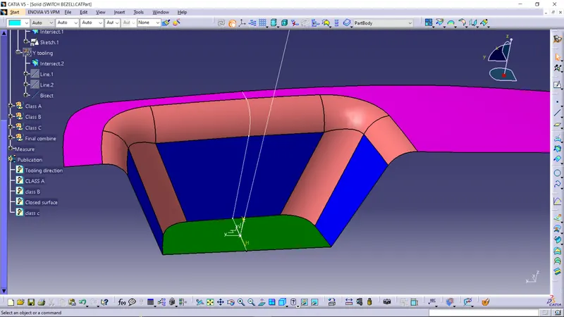
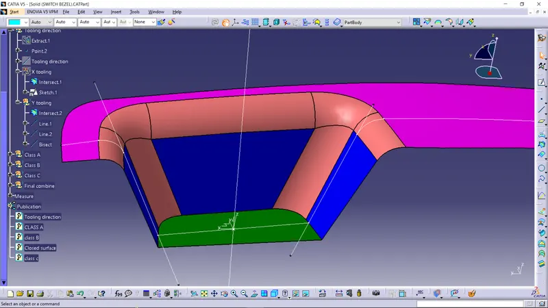
The blue dotted line is the final tooling axis
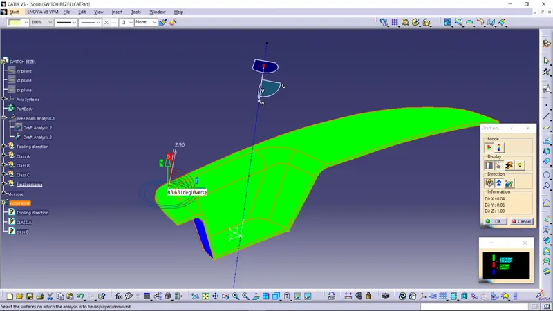
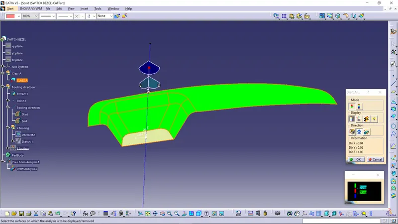
Draft analysis of class A surface:
All the green region have draft angle above 3.0
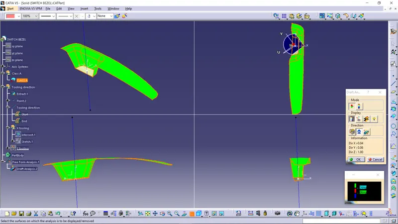
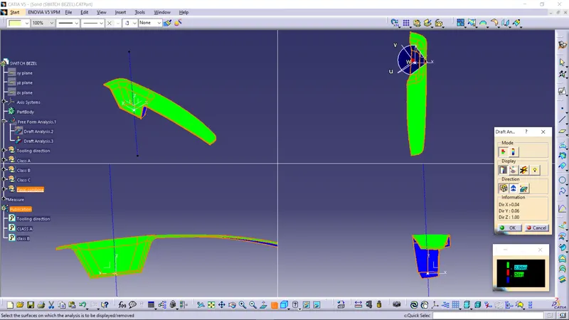
Draft analysis of Solid switch bazel:
All the green region have draft angle above 2.95