Week 8 - Challenge 2 - Switch Bezel Design
AIM:
Create the Switch Bezel Plastic component through the given Class-A surface. To begin with, the tooling axis for the given Class-A Surface should be created meeting the requirements of the draft angle and at the end perform the Draft analysis on the model.
Take the Thickness of the component to be 2.5 mm
CHALLENGE EXPECTATIONS:
- Tree Structure
- Ensure Proper Tree Structure
- Geometrical sets should have a proper name based on the sketches present inside of it
- All the sketches should be created under the Geometrical set
- Use the Close Surface feature to make a solid body from the surface.
- Publications: Use the publication option and publish the below
- Tooling Axis
- Class A, B, and C surface
- Report
- A detailed report should be done explaining the draft analysis and the tooling axis creation.
- An explanation should be given on the way of creating the tooling axis, particularly the Bisecting method.
Step-1
Checking Surface integrity of received Styling Surface and extracting Class A surface.
Step-2
Creating Tooling Direction and checking with draft analysis.
All surface meets 3-degree minimum draft angle criteria.
Step 3
Creating B surface at an offset of 3mm from class A surface( styling surface)
Step 4
Creating Class C surface joining Class A and Class B surface.
Step 5:
Final trimming of A, B, and C surface to obtain a closed surface. The profile is checked for any open edges. Class A surface is corrected for edge correction and the final trim is obtained again to create a solid body from the surface.
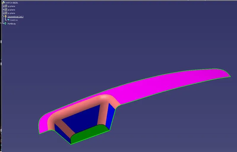
Given body
DRAFT ANALYSIS:
The Draft analysis is performed based on color ranges identifying zones on the analyzed element where the deviation from the draft direction at any point, corresponds to specified values. Here I am taking the draft angle of 0 to 2.6 degrees.
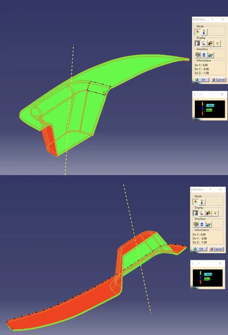
DRAFT ANALYSIS
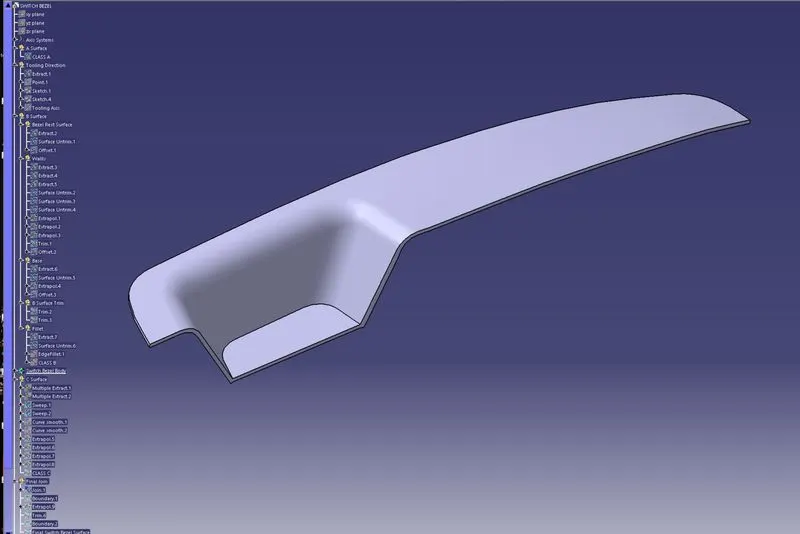
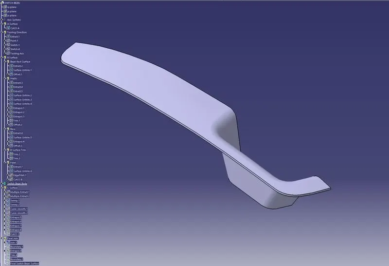
(a) ISOMETRIC VIEW (b) ISOMETRIC VIEW
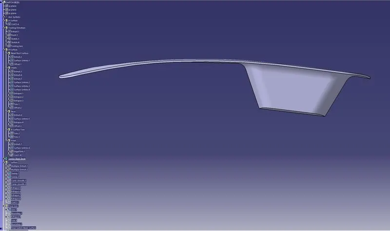
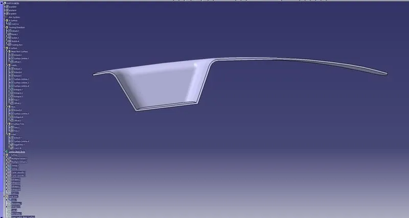
(c) Front view (d) Back view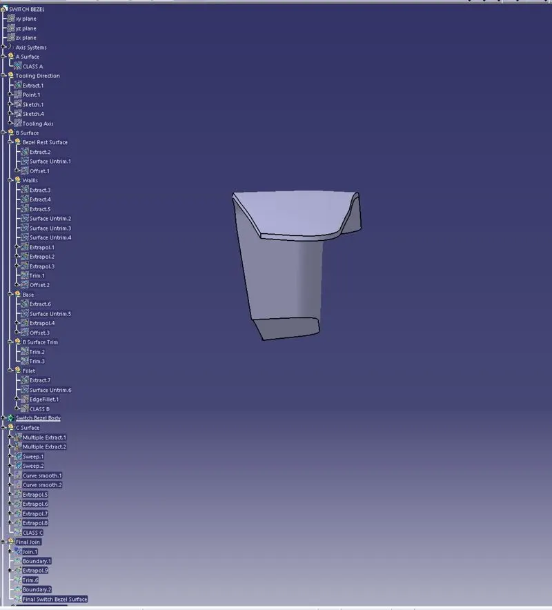
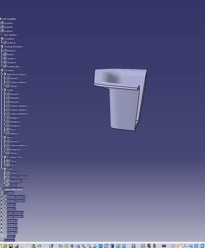
(e) LHSV (f) RHSV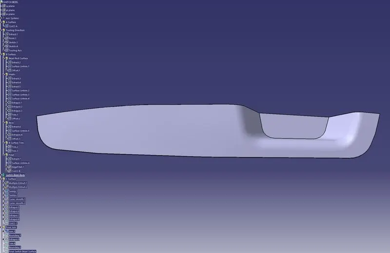
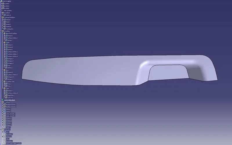
(g) TOP VIEW (h) Back view