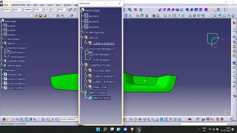
MODELING OF SWITCH BEZEL FROM CLASS A SURFACE USING CATIA
REPORT
SWITCH BEZEL
Aim: To create a plastic switch bezel component from the given Class A surface
Methodology: The steps followed are as mentioned below
- Tooling axis is created
- Draft analysis is performed
- Class-B surface is generated
- Class-C surface is generated
- A closed solid model is created from the serfaces.
Tooling axis
- The first step is to ensure that the given surface is a closed surface. This can be fixed by using the join option. For verification use the join tool or the boundary tool.
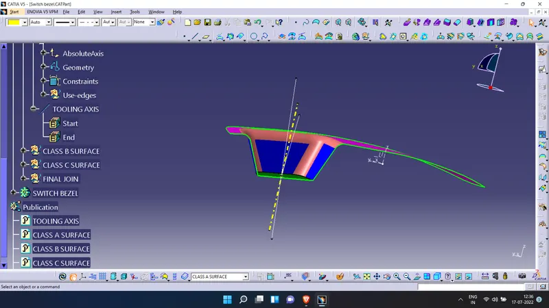
- An axis for the tooling direction is decided through visual inspection.
- The tooling direction in this model will be created paralell to the Z direction. For this a point is inserted in the extrated base surface of the component. An axis sytem is inserted along this direction.
- Now 2 sketches are drawn along the ZY plane and ZX plane and the intersections of the class a surface is created. For the sketch along ZY plane the slanting edges in the intersection is extrapolated with 2 lines and a bisecting line is created.
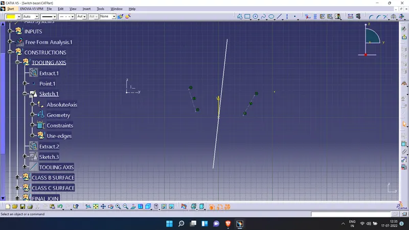
- For the sketch along the ZX plane the slanting edge of the intersection is extrapolated with the line tool and a new line is drawn passing through the point created. These two lines will be at angle of 6°.
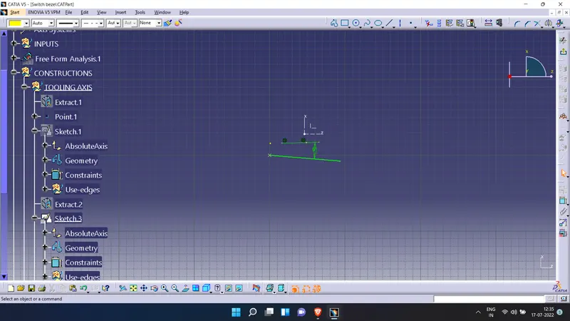
- A new line will be created which bisects the 2 lines from the sketches created previously. This line represents the tooling axis.
Draft analysis
- The surface to the analysed is selected and the material options is turned on in the customize option.
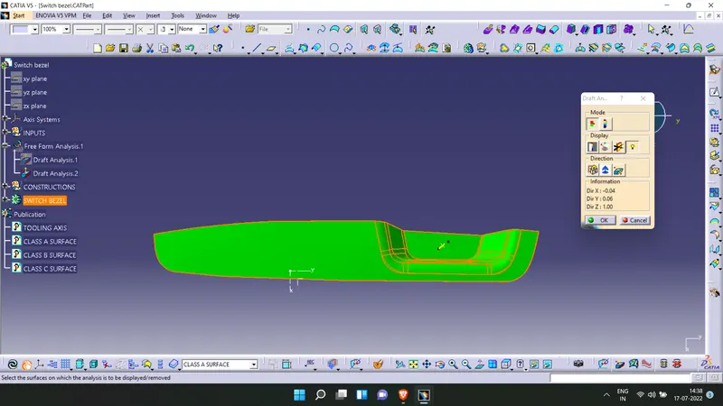
- The feature draft analysis tool is opened.
- The compass is aligned with the tooling direction.
- It is made sure that the pulling direction is correct. Otherwise it is flipped from the open toolbar.
- The surface is selected to make sure that the draft values are in permissible limits on all faces.
Draft analysis of class A surface
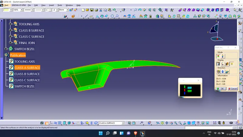
Draft analysis of plastic component.
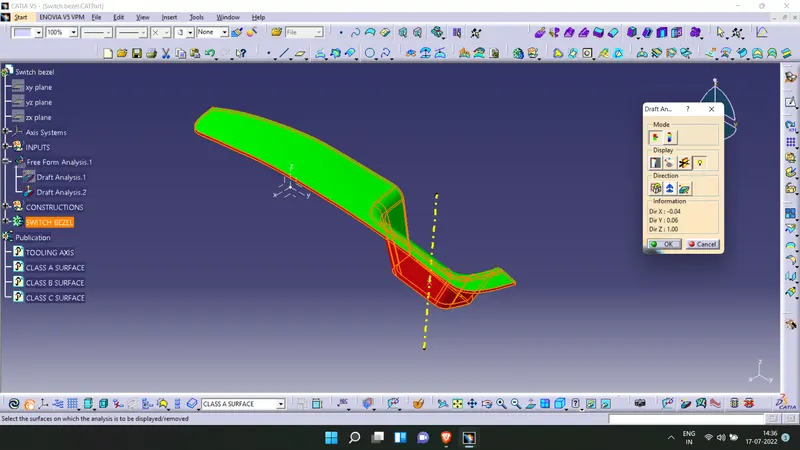
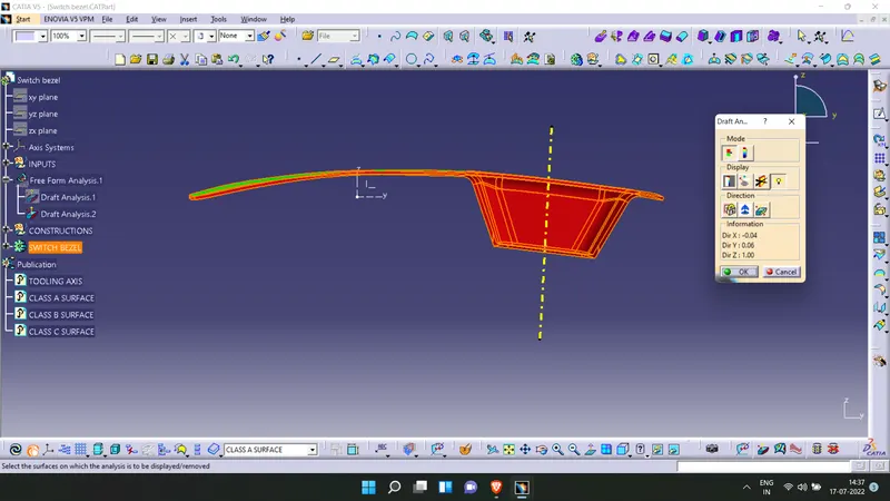
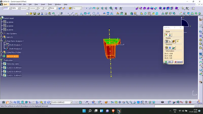
Feature Tree