MODELING OF SUNSEEKER PREDATOR YACHT USING SOLIDWORKS
1. Radar Mast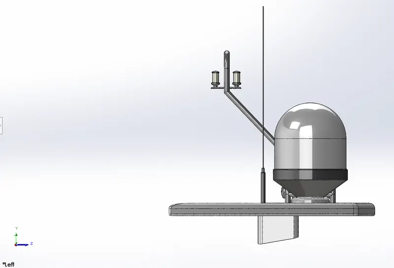
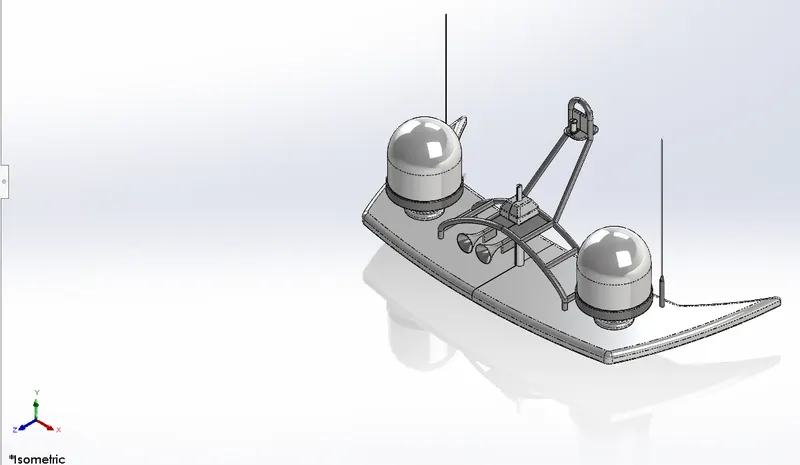
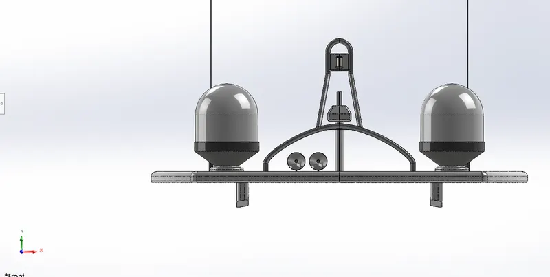
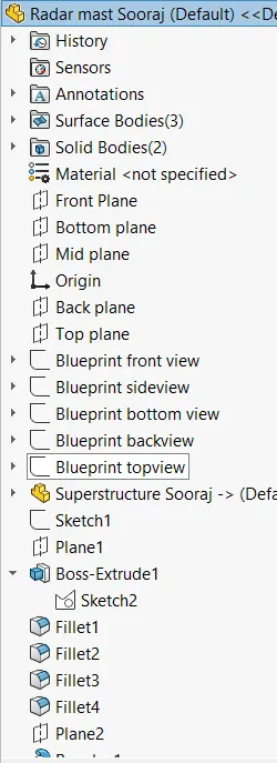
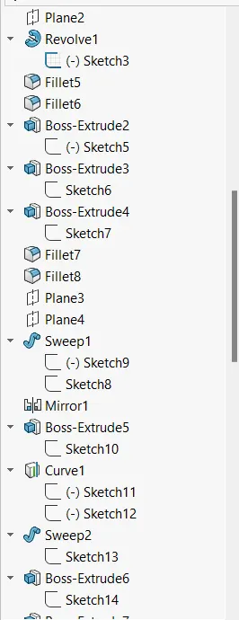
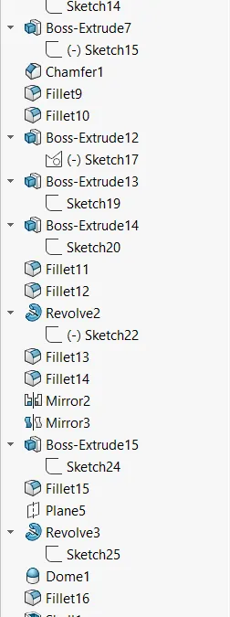
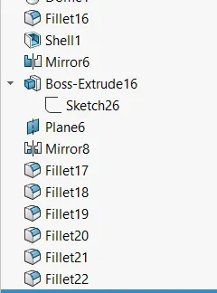
2. Yacht Assembly
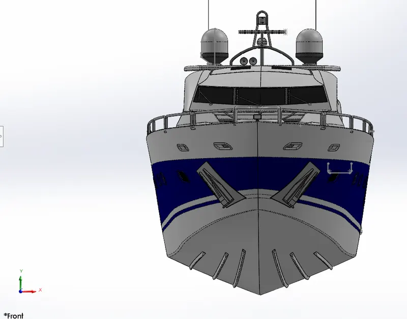
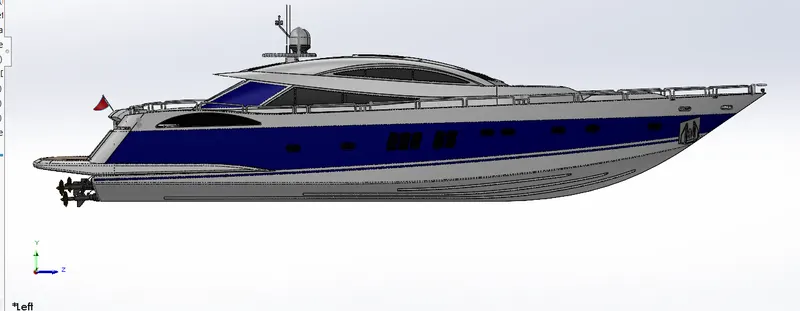
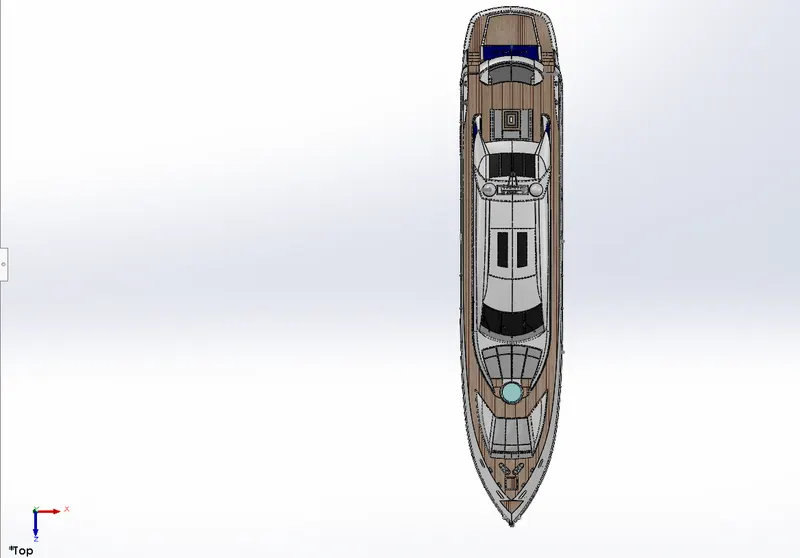
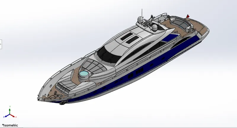
3.
REPORT
SUNSEEKER PREDATOR YACHT
OBJECTIVE
To model a sunseeker predator yacht using SOLIDWORKS 2022 and create realistic renderings using Photoview 360.
INTRODUCTION
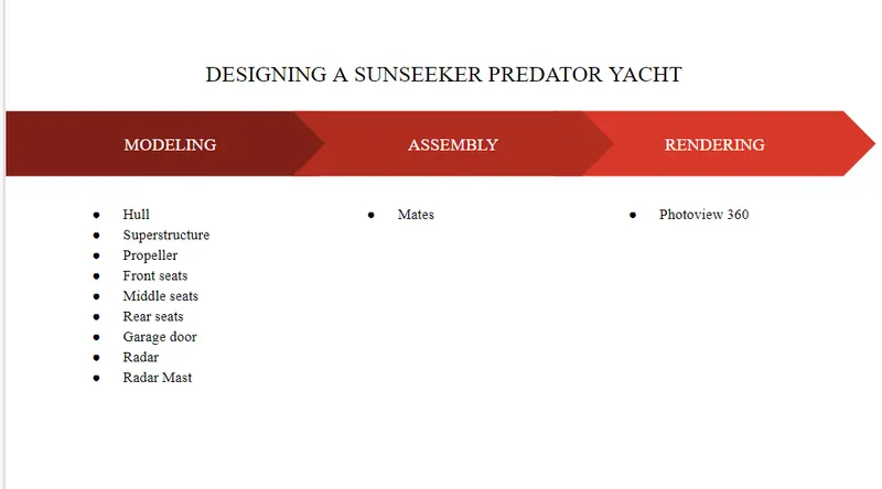
The goal of this project is to use a cosmetic model of a Sunseeker Predator Yacht to explore the capabilities of SOLIDWORKS and become familiar with all its tools and features. Modeling, assembly, and rendering are the primary parts of the project.
DESIGN METHODOLOGY
Surface Modeling (Part modeling)
Most of the components were modeled through a surface modeling approach. Surface modeling enables creating complex geometric models with ease.
The important features used for modeling the yacht are as follows.
- Lofted Surface: A smooth 3D loft is created between two 2D sketches.
- Swept Surfaces: A surface is swept through the desired patch based on a 2D sketch drawing.
- Surface Fill: Used to close patches between surfaces by creating a relation between the edges of the patch.
- Surface Trim. Used to trim off surfaces based on a desired sketch or profile.
- Extend Surface: Used to elongate the surface based on a desired selected edge or contour.
- Surface Knit: Used to knit the edges of two surfaces together and hence reduce the gap between them.
- Sketch: Used to draw 2D or 3D sketches using sketching tools.
- Revolve Boss/Bass: Used to create revolves and generate 3D material about an axis of revolution based on the selected sketch profile.
- Mirror: Used to mirror and generate identical bodies, surfaces, or sketches along a selected mirroring surface.
- Projection Curve: Used to integrate the attributes of two curves from two separate planes into a new curve in 3D.
- Appearance: By adding colors and other elements, this tool is utilized to give the constructed models realistic appearances and attributes.
- Filet: To make the edges less sharp, the Fillet tool is used to round them off.
- Shell: By eliminating the material inside according to the appropriate thickness, this feature can be utilized to construct a shell of a solid model.
- Dome: This function uses a dome-shaped 3D extrusion to shut off open or closed ends or surfaces.
- Boss Extrude: With regard to the sketch plane, this characteristic is utilized to linearly extrude 3D material from the 2D sketches.
- Extrude Cut: Utilizing this tool, sketches created on the sketch plane are cut through the 3D material along a straight path.
- Split: Using a sketch created on a sketch plane and projecting it linearly onto a 3D surface or body, this tool may divide a 3D substance into two pieces.
Components designed
The designed elements are listed below, along with their rendered images, explanations, and design tools.
- Hull
- Superstructure
- Propeller
- Front seats
- Middle seats
- Rear seats
- Garage door
- Radar
- Radar Mast
- Hull
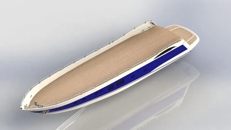
The hull is the largest component of the entire assembly featuring a lot of surface features and sketch features. Most of the other components are modeled based on the deck surface of the hull. This makes assembly and mating easier.
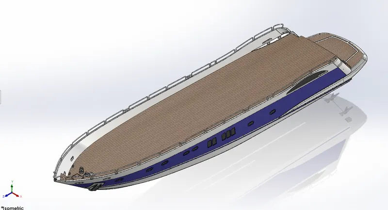
The features used are:
- Sketch
- Project Curve
- Swept Surface
- Surface Extrude
- Swept Boss/Bass
- Extrude Boss/Bass
- Surface trim
- Mirror
- Appearance
- Fillet
- Chamfer
- Surface Extend
- Pattern
- Superstructure
The superstructure is the next most largest and time-consuming component to create of all. A surface modeling approach was used to model the superstructure. The hull deck reference was used to model the entire superstructure. On finishing the surface modeling the entire body was knitted and a solid was created out of it.
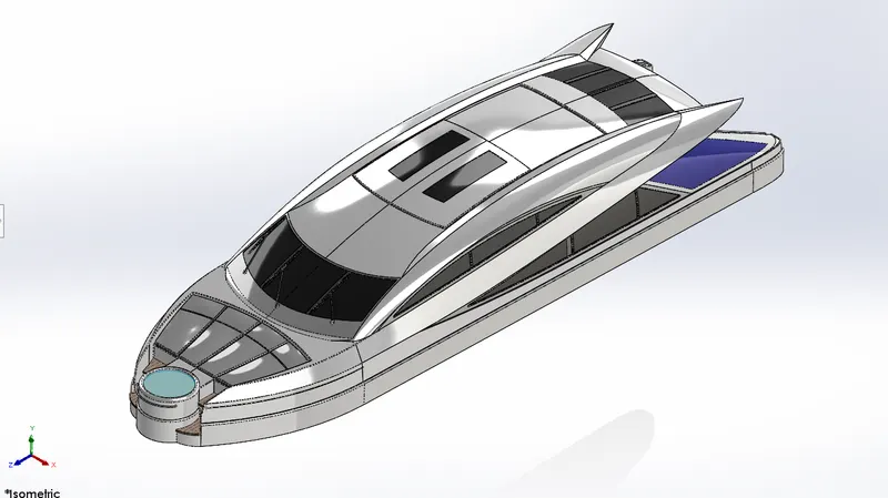
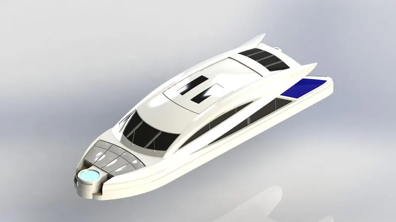
The features used are:
- Sketch
- Project Curve
- Swept Surface
- Surface Extrude
- Swept Boss/Bass
- Extrude Boss/Bass
- Surface trim
- Mirror
- Appearance
- Fillet
- Chamfer
- Surface Extend
- Pattern
- Lofted Surface
- Delete Surface
- Surface Knit
- Surface Fill
- Propeller
The propeller was the easiest component of the model. It is mated with the hull. It is meant to propel the yacht through water by rotating.
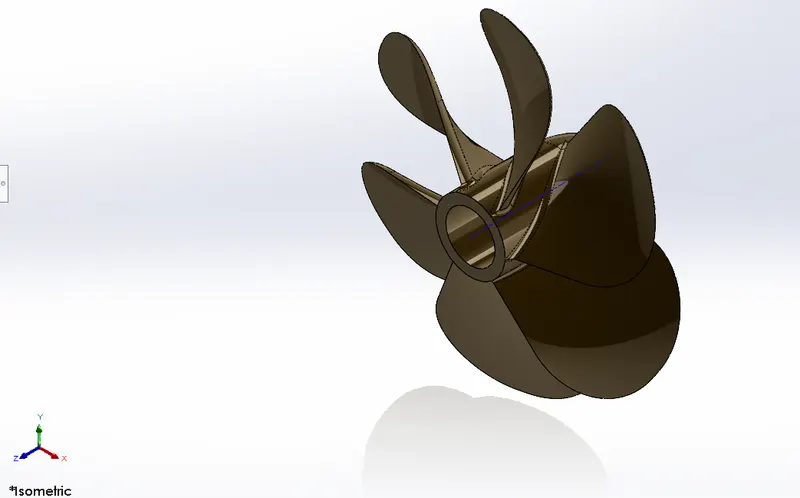
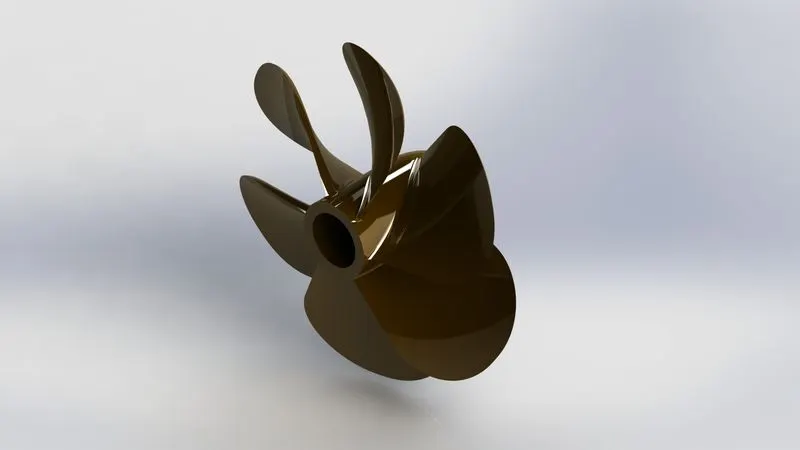
The features used to model a propeller are
- Sketch
- Revolve
- Cut Extrude
- Fillet
- Circular Pattern
- Front Seats
The front seats are modeled with reference to the deck of the hull. Hence mating the components together in the assembly stage was easy.
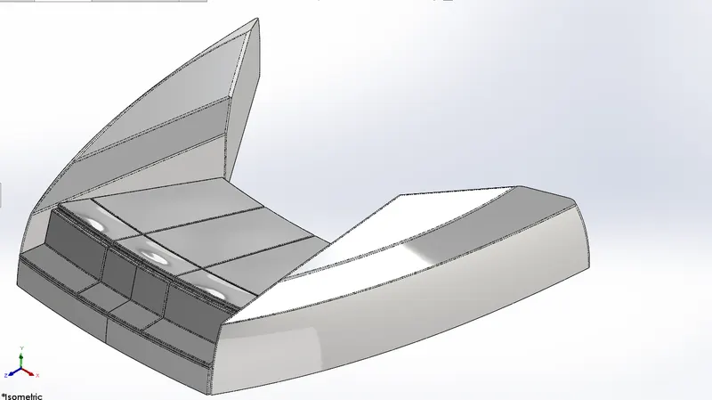
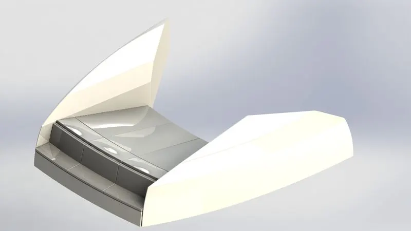
The features used to model the front seats are
- Surface Loft
- Surface Knit
- Surface Trim
- Surface Extend
- Surface Fill
- Surface Sweep
- Chamfer
- Fillet
- Revolve Boss/Bass
- Cut Extrude
- Dome
- Sketch
- Mirror
- Middle Seats
The middle seats were also modeled by importing the deck of the hull for reference. The middle seats are placed under the superstructure. It consists of seating arrangements along with a table-like structure.
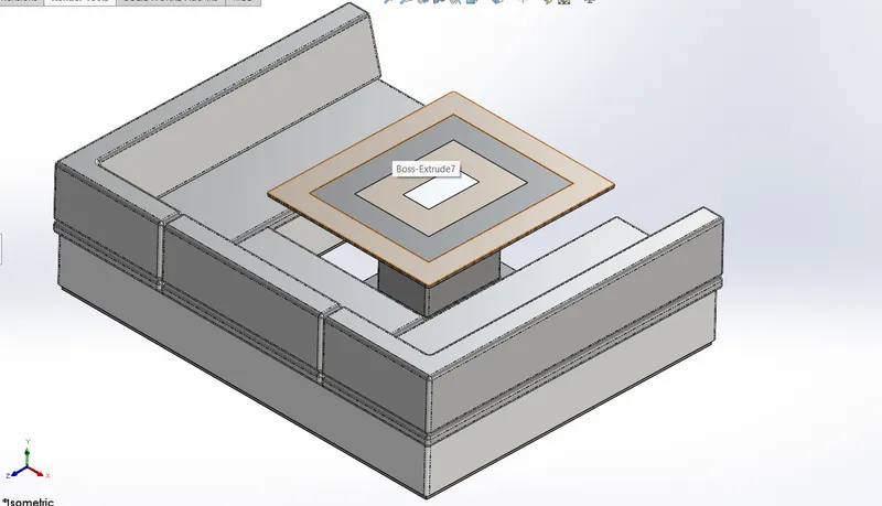
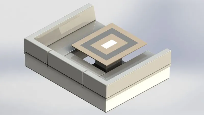
The Feature used to model the middle seats are
- Fillet
- Sketch
- Mirror
- Extrude Boss/Base
- Cut Extrude
- Appearance
- Rear Seats
The rear seats are mated close t the end of the deck. It has a lot more features than the front and middle seats. The rear seats also have a small flag post attached to them. Most of the features used till now were also used for the rear seats.
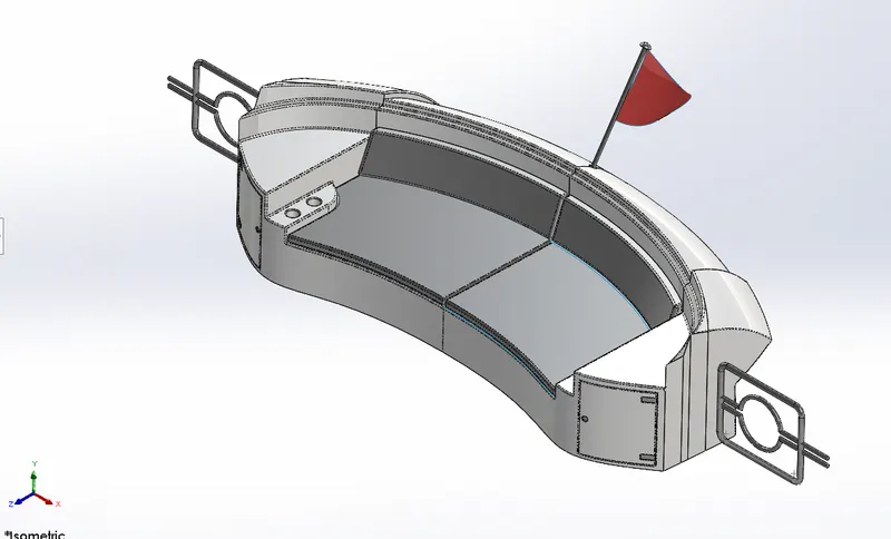
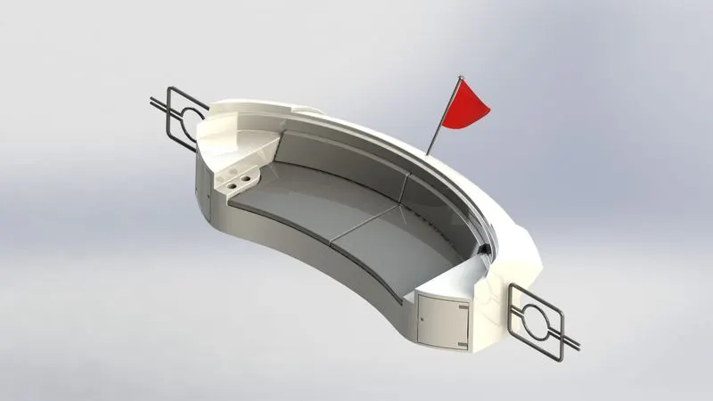
The features used are
- Fillet
- Sketch
- Mirror
- Surface Loft
- Surface Knit
- Swept Boss/Bass
- Extrude Boss/Bass
- Surface Trim
- Surface Extend
- Surface Fill
- Surface Sweep
- Extrude Boss/Base
- Cut Extrude
- Appearance
- Garage door
The garage door was modeled out of a cutout 3D extrude of the Hull. It is the simplest and least time-consuming component of the model of all the.
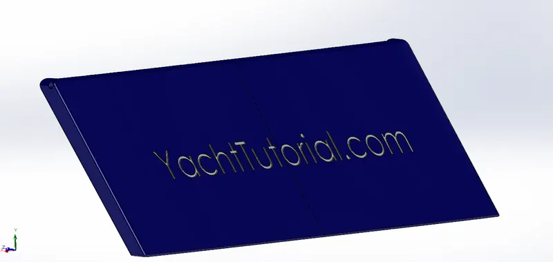
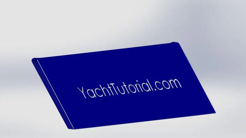
The features used are
- Extrude Boss/Bass
- Fillet
- Chamfer
- Appearance
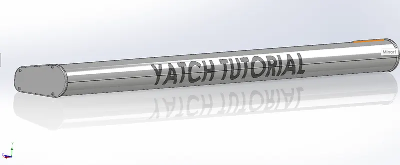
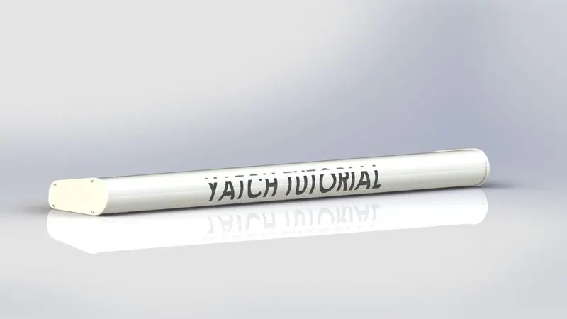
- Radar
The Radar is also an easy and least time-consuming component of the model. It is attached to the Radar mast of the Yacht. The Radar is used for mapping positioning.
The features used to model the Radar are
- Extrude Boss/Bass
- Fillet
- Chamfer
- Mirror
- Sketch
- Appearance
- Radar Mast
The Radar mast is the final component of the model. It was modeled with reference to the top surface of the superstructure. This made it easy to insert and assemble the components.
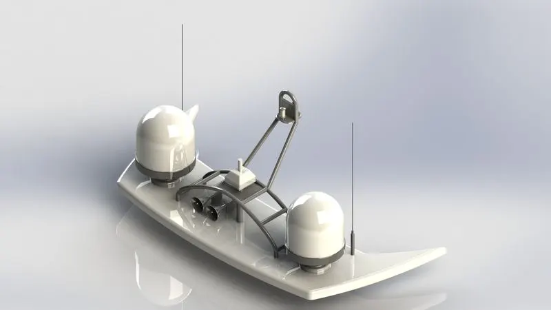
The features used to model the Radar mast are
- Fillet
- Sketch
- Revolve Boss/Bass
- Mirror
- Extrude Boss/Base
- Shell
- Cut Extrude
- Appearance
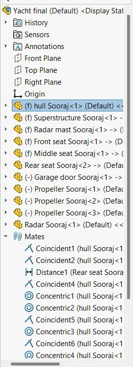
Assembly
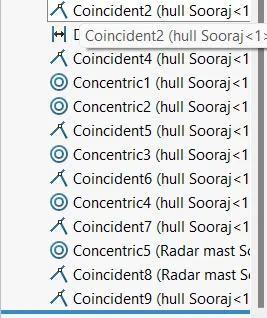
The components that were developed and saved separately must now be put together. Each component is brought to the assembly workstation separately and connected to the others. A variety of ways to put the various parts together are offered by the mate option. The model can be saved and used for rendering once the assembly is finished.
Rendering
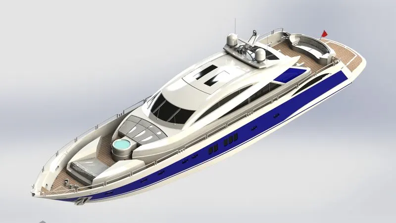
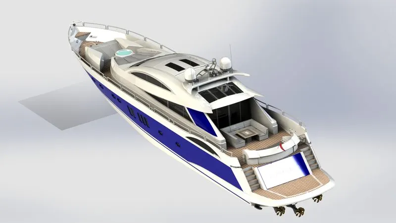
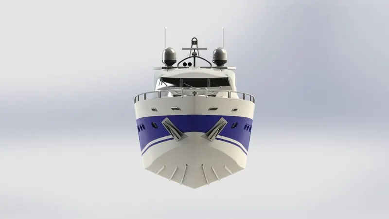
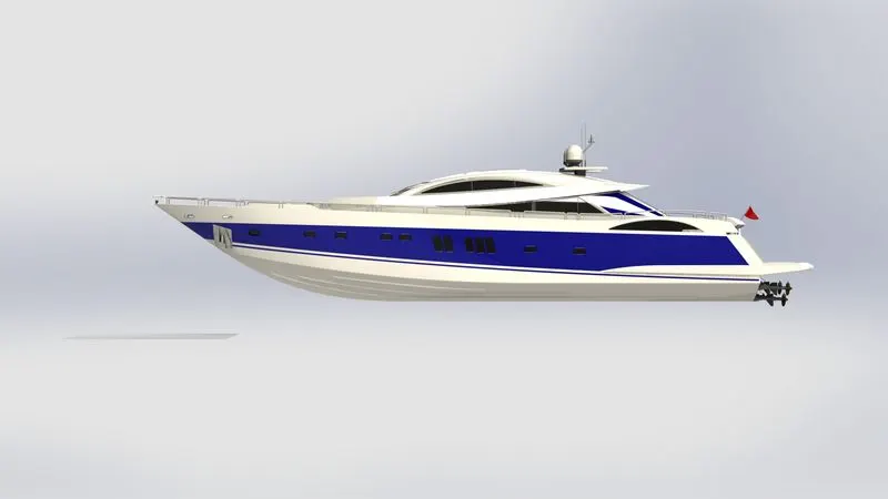
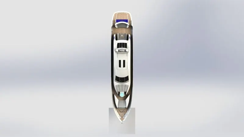
After assembly, the final renders are made using photo view 360, a rendering tool within SOLIDWORKS 2022. The final renders are attached in this report.
CONCLUSION
A Sunseeker Predator Yacht was modeled, assembled, and rendered. The photo-realistic renderings were made using the photo view 360 tools inside SOLIDWORKS 2022. The part files and rendered images are attached to the report.