MODELING OF FAN BASE BRACKET FROM CLASS A SURFACE USING CATIA
REPORT
BASE BRACKET
Aim: To create a solid model from the given class A surface
Methodology: The procedure followed is as mentioned below
- Tooling axis is identified
- Draft analysis is performed
- Class-B surface is created
- Class-C surface is created
- Solid model is made from the final surface
Creation of tooling axis
- The class a surface should be completely joined. This is ensured by using the boundary or join tool,
- The most suitable direction for tooling is analysed visually.
- The direction from which we can see the holes propelry is usually chosen as the direction if the tooling axis. So the z axis direction is chosen and a dummy tooling axis is created.
- Inorder to make sure that no sides od the surface will create an issue while tooling an intersection of the surface is made with the YZ plane. 2 lines are extrapolated through the 2 surface intersections and a bisecting line is created.
- The bisecting line is collinear with the dummy tooling axis and is the appropriate tooling direction for this model.
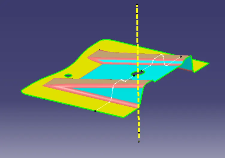
Dummy tooling axis and intersection curve
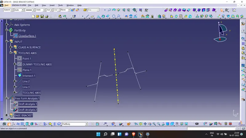
Final tooling axis obtained through the intersection method.
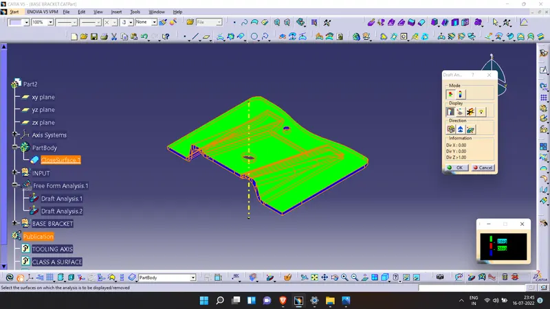
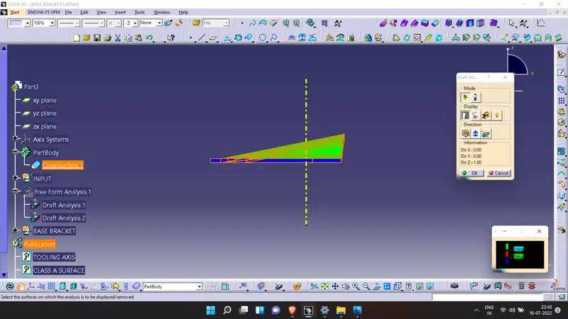
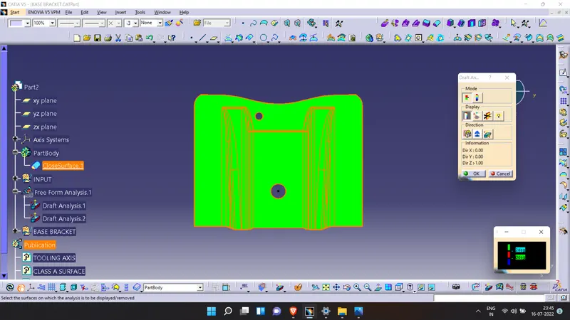
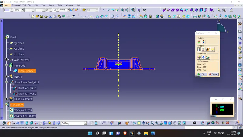
Draft analysis
- The feature draft analysis tool is opened.
- The compass is aligned with the tooling axis
- The surface is selected.
- It is verified that the surfaces are within the permissible levels of drafts values.
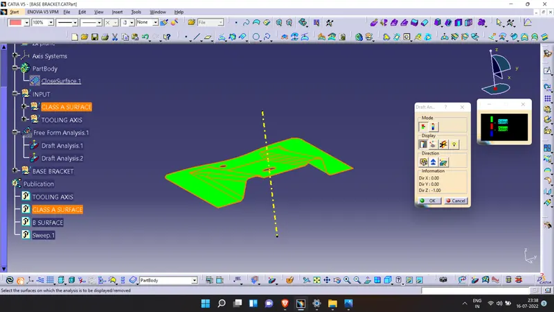
Draft anslysis of class A surface
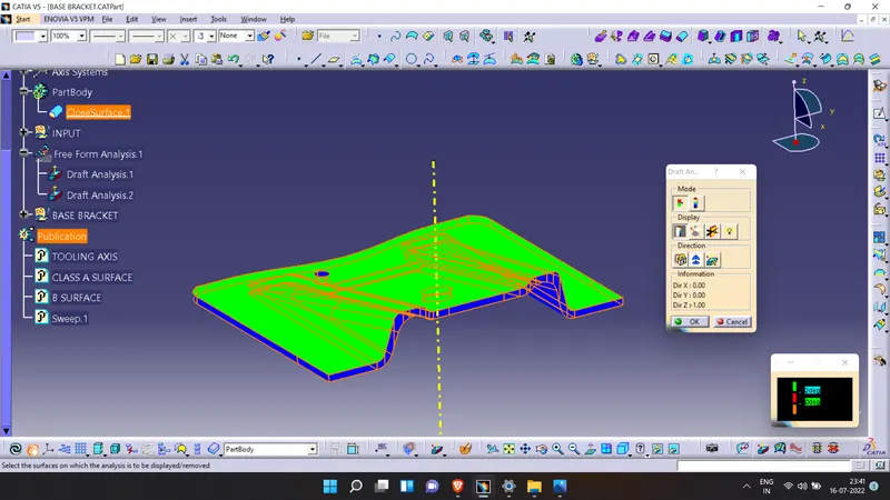
Feature Tree
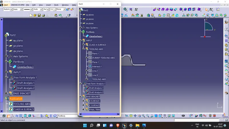
.