MODELING OF AMERICAN CHOPPER USING SOLIDWORKS
1. REPORT
DESIGN OF AMERICAN CHOPPER USING SOLIDWORKS
OBJECTIVE
To design an American chopper using the software SOLIDWORKS and to create photorealistic renderings using SOLIDWORKS Visualize.
INTRODUCTION
SOLIDWORKS is a powerful tool. This project attempts to explore the potential of SOLIDWORKS and familiarize with all the tools and features by sketching, creating, and assembling a cosmetic model of an American chopper. The project consists of mainly 3 phases; modeling, assembling, and rendering.
DESIGN METHODOLOGY
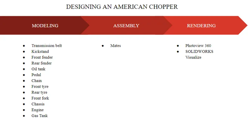
Flow chart
Part Modeling
Part modeling is the first step in creating a 3D model using CAD. A 2d dimensional sketch of the model is created and then it is converted to a 3D model using the tools under the features tab in SOLIDWORKS. The important tools used for this project are as follows
- Boss Extrude: This feature is used to extrude 3D material linearly from the 2D sketches with respect to the sketch plane.
- Extrude Cut: This tool is used to cut through the 3D material linearly along the sketches drawn in the sketch plane.
- Fillet: The Fillet tool is used to round off the edges to make them less sharper.
- Lofted Boss/Base: This tool is used to join two 2D sketches on 2 different surfaces by filling in 3D material between them linearly.
- Split: This tool is used to split a 3D material into 2 using a sketch drawn on a sketch plane by projecting it on the 3D surface or body linearly.
- Dome: This feature is used to cap off open or closed ends or surfaces using a dome shaped 3D extrude.
- Shell: This feature is used to create a shell of a solid model by removing the material inside based on the desired thickness.
- Combine: The combine feature is used to combine 2 solid bodies and create a new one that integrates physical features of the used 2 bodies.
- Chamfer: The chamfer feature is used to taper off edges of 3D models by cutting off the material.
- Linear Pattern: The linear pattern tool is used to create copies of a feature along a linear path according to our desired factors like distance between instances, number of instances etc.
- Circular Pattern: Similar to the linear pattern tool, here the pattern created will be along a circular path and not linearly.
- Revolve Boss/Base: This feature is used to revolve 2D sketches with respect to the desired axis and hence create cylindrical-shaped 3D models of the sketch.
- Revolved Cut: This feature is used to cut out material through a circular path along the desired axis from 3D models.
- Move/Copy Body: Used to move or copy bodies from one point to another.
- Mirror: This feature is used to create a mirror replica of a 3D model with respect to the desired axis.
- Sweep: This feature is used to sweep a 2D sketch along the desired path in 3D creating an extruded 3D model.
- Sweep Cut: This feature is used to cut out 3D material through a 2D sketch along the desired path in 3D.
- Swept Surface: Used to sweep and create surfaces along a path through a 2D line or curve.
- Boundary Surface. Used to generate a boundary surface between two existing surfaces.
- Loft Surface: This feature is used to generate 3D material between 2 profiles along the desired path.
- Knit Surface: Used to join 2 surfaces together and reduce the distance between them by knitting them together.
- Surface Trim: Used to trim out material from Surfaces.
- Projection Curve: Used to project two curves from 2 different planes and create a new curve in 3D integrating the properties of the curves together.
- Blocks: This feature is used to create fundamental units of large models. They can be saved, inserted, and edited wherever needed.
- Trim Entities: Used to trim off unwanted lines and edges in the drawings.
- Appearance: This tool is used to give the models created realistic appearances and features by inserting colors and other features.
Assembly
The next step is to assemble all the parts that were created and saved separately. Each part is individually introduced to the assembly workbench and mated with each other. The mate option provides a number of ways to assemble the different components together. Once the assembly is completed the model can be saved and used for the rendering process.
Rendering
Rendering can be done mainly using 2 different tools in Solidworks, the photo view 360 tool and the Solidworks Visualize tool. The assembled model can be set up in different backgrounds and all the visual properties can be adjusted and manipulated to create renders with desired properties.
Components designed
The components designed along with their rendered images, descriptions, and tools used to design them are as mentioned below.
- Transmission belt
- Kickstand
- Front fender
- Rear fender
- Oil tank
- Pedal
- Chain
- Front tire
- Rear tire
- Front fork
- Chassis
- Engine
- Gas Tank
- Transmission belt
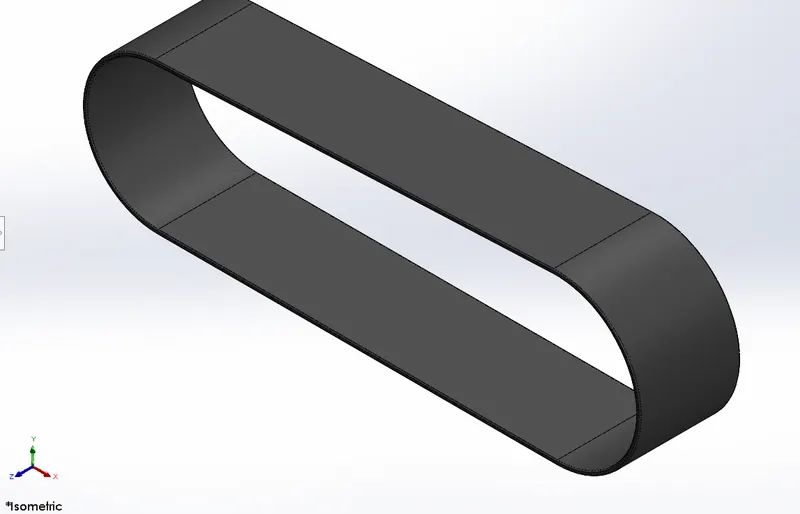
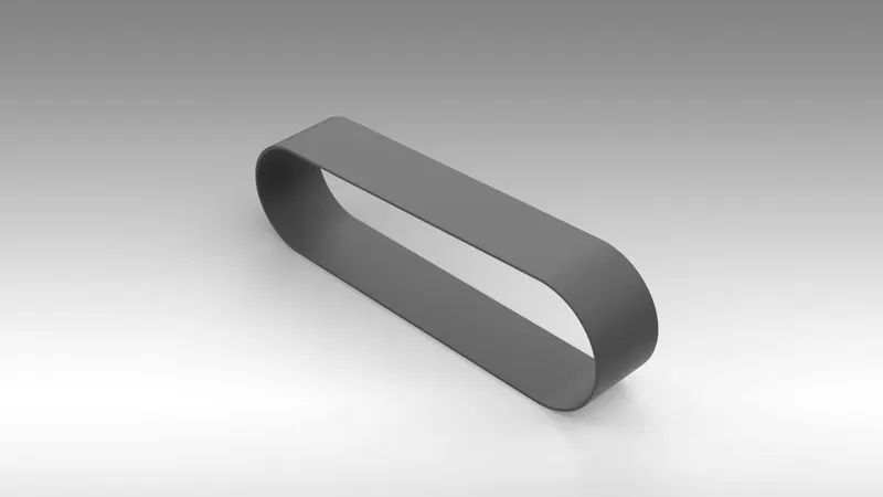
The transmission belt was the easiest component designed in this project using SOLIDWORKS. The belt is used to join the pulley system in the engine. It was designed using very basic tools like line, arc, offset, etc.
Features used
- Offset Entities
- Extrude
- Fillet
- Appearance
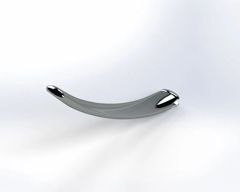
- Kickstand
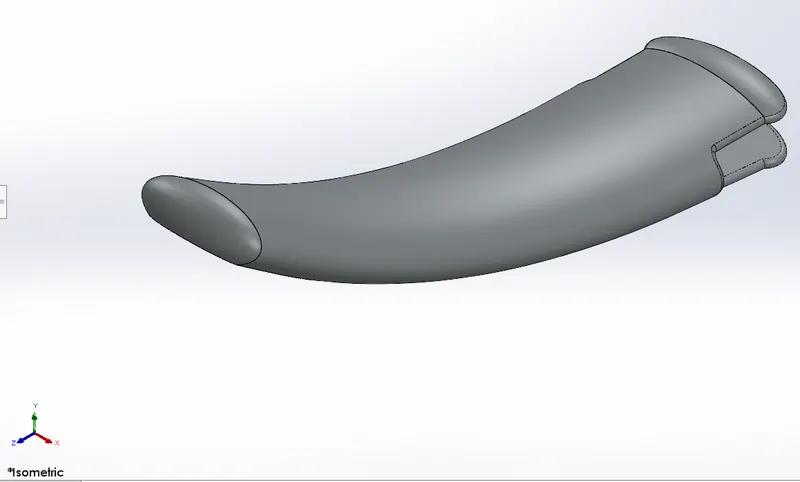
The kickstand was again another easy component designed. It is one among the only few moving components of the entire assembly. The movement was set using the mate tool during assembly. New features like dome and split were used in modeling this component.
Feature used
- Loft Boss
- Extrude Boss
- Extrude Cut
- Split
- Dome
- Fillet
- Appearance
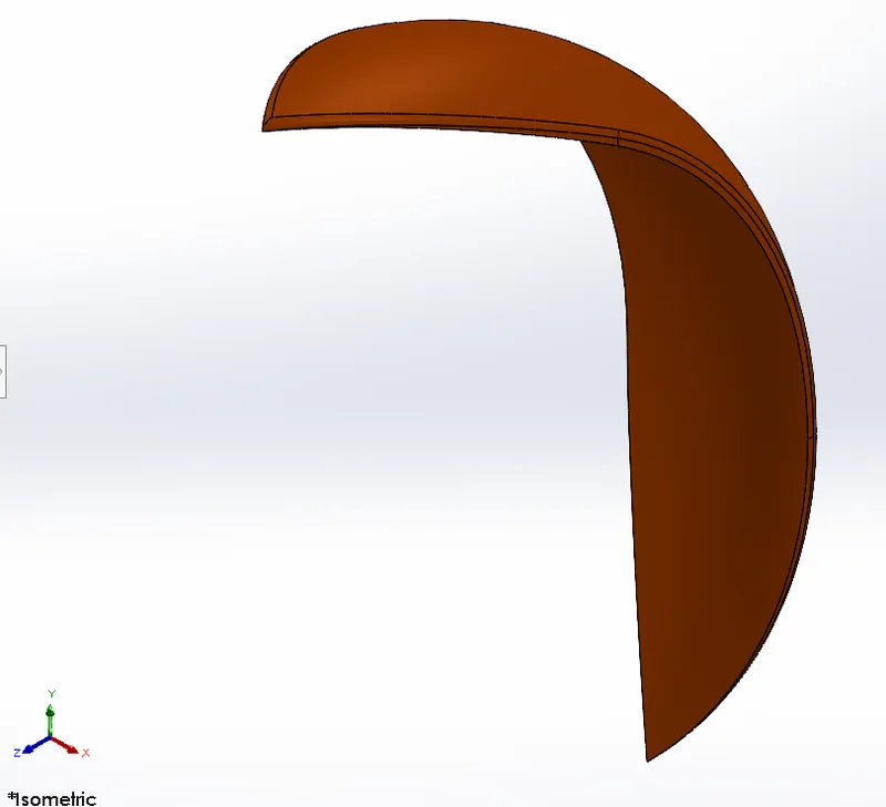
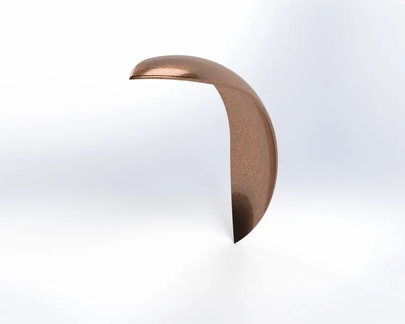
- Front Fender
The front fender was created as a single solid body using the revolve tool. Other features were added to the single body using the trim and mirror tools.
Features used
- Revolve boss
- Mirror
- Trim entities
- Fillet
- Appearance
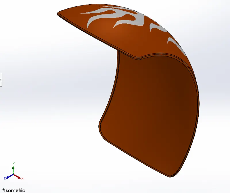
- Rear Fender
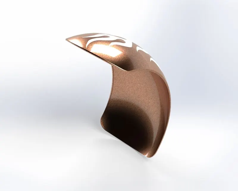
The rear fender was created in a way similar to that of the front fender. A single body was created by the revolve tool and other features were added. The Rear fender was completed by adding decals.
Features used
- Revolve boss
- Trim entities
- Offset entities
- Appearance
- Decals
- Chain
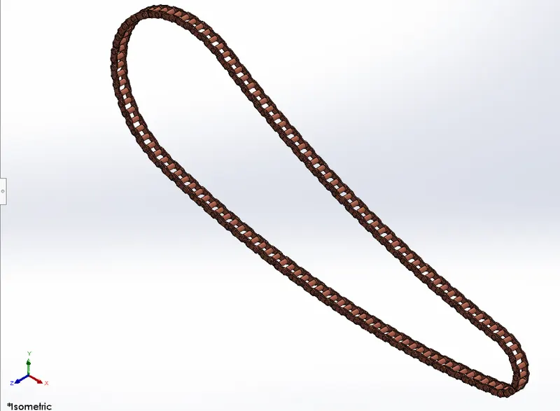
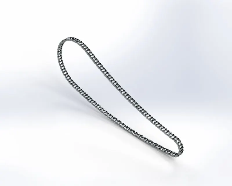
The chain was the most complex component of all. It was created by using the block feature to create repetitive units and join them with the curve-driven pattern tool. Each unit was set as an individual body to maintain its realistic appearance.
Features used
- Block
- Trim entities
- Extrude
- Curve driven pattern
- Fillet
- Appearance
- Oil Tank
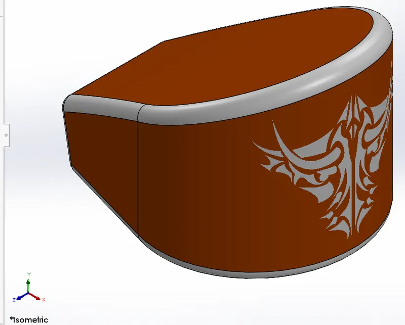
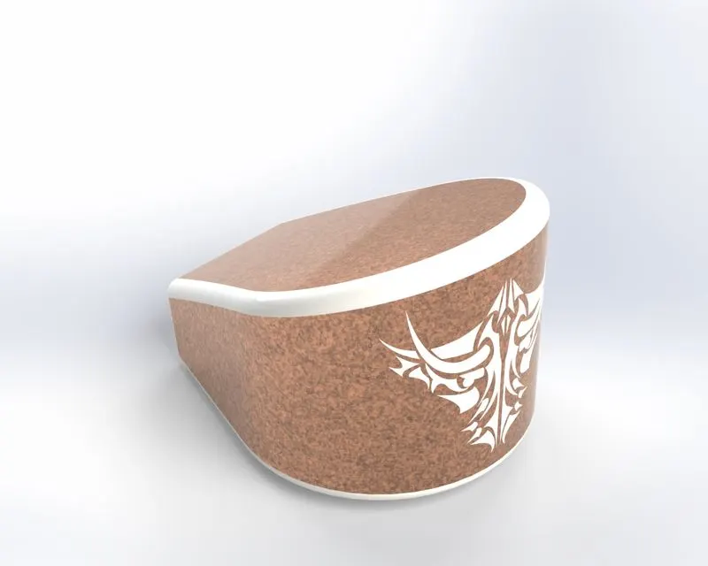
The oil tank is in a single solid body. It was modeled using new tools like combine and shell. To complete the appearance decals were added in the end.
Features used
- Combine
- Extrude boss
- Shell
- Fillet
- Appearance
- Pedal
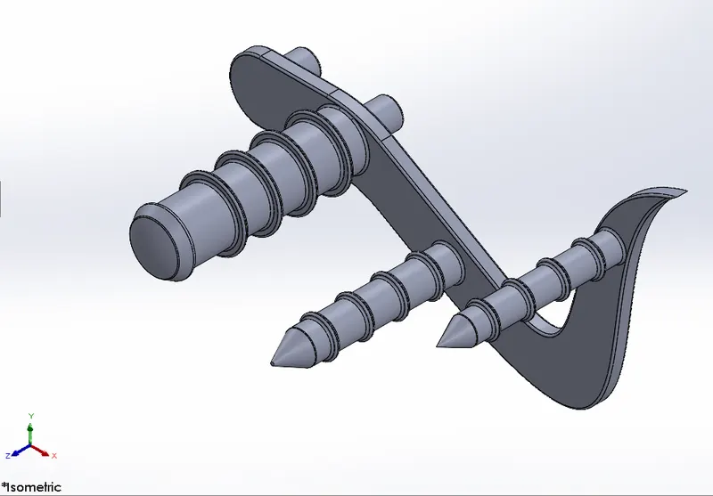
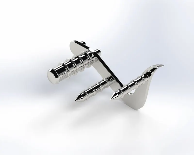
The pedal was created only for the right side of the chopper. The component created was mirrored during the assembly process for the left- side of the chopper. A number of curves were used to model the pedal.
Feature used
- Extrude boss
- Fillet
- Linear pattern
- Dome
- Chamfer
- Appearance
- Front-wheel
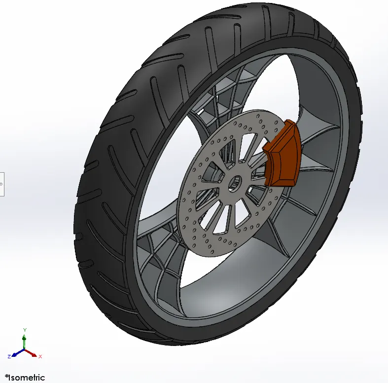
The front wheel is a multi-body component consisting of the tire, rotor, disc caliper, and rim. The component was modeled using a number of tools. The appearance was given by coloring each part of the component separately.

Features used
- Revolve boss
- Trim entities
- Fillet
- Revolve cut
- Linear pattern
- Chamfer
- Cut extrude
- Circular pattern
- Appearance
- Rear-wheel
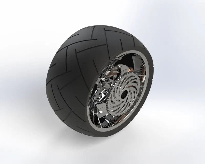
The rear wheel was modeled similarly to the front wheel. Most of the tools used were common. The rear wheel has an additional component which is the chain sprocket. The rear wheel is smaller in diameter but thicker in nature when compared to the front wheel.
Features used
- Revolve boss
- Trim entities
- Fillet
- Revolve cut
- Planes
- Linear pattern
- Chamfer
- Cut extrude
- Circular pattern
- Appearance
- Front Fork.
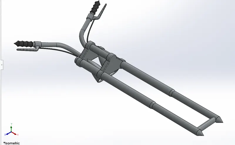
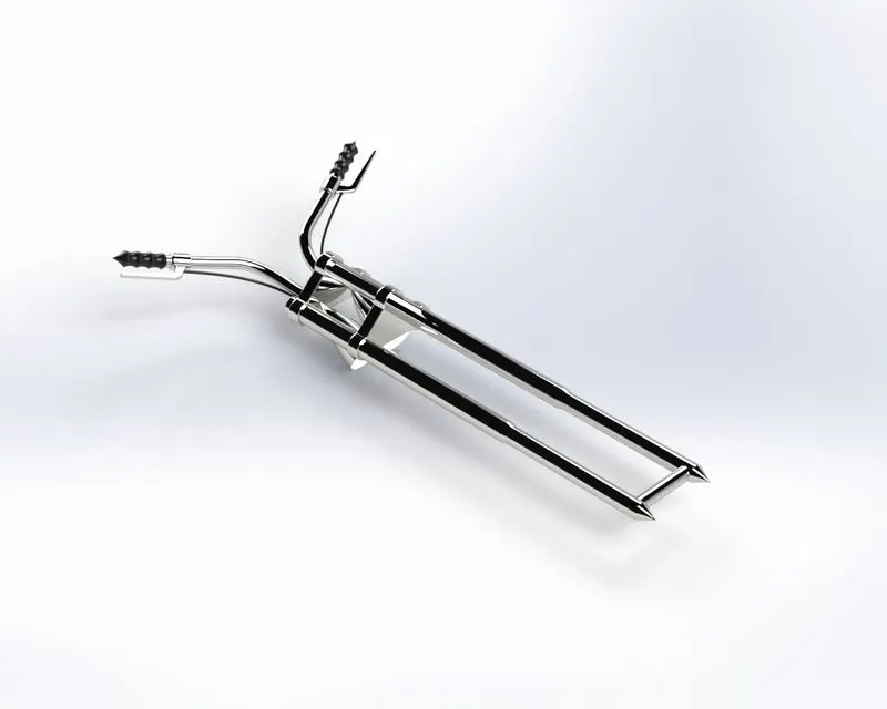
The front fork has unique features when compared to the other components. It is the second moving component of the entire assembly. The lights of the front fork were designed by incorporating the lights from the appearance tab. Several new planes were created to design as well as assemble the fork with the chassis.
Features used
- Revolve boss
- Extrude boss
- Fillet
- Split
- Planes
- Dome
- Move/copy
- Mirror
- Combine
- Projected curve
- Sweep boss
- Appearance
- Chassis
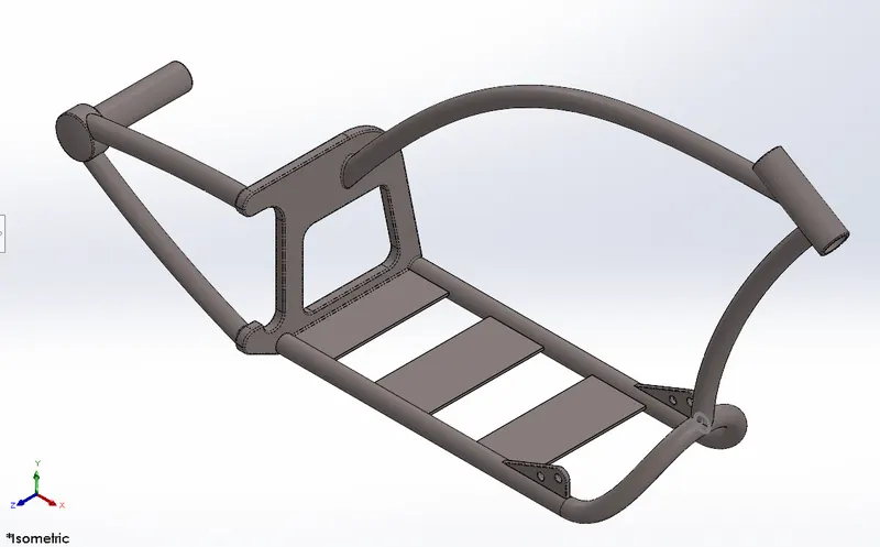
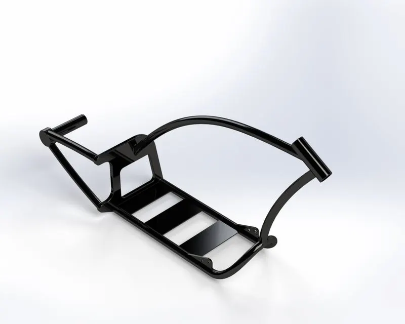
The chassis is a single body component. It is the most important component of all when it comes to assembly. Most of the components were assembled with respect to the chassis.
Features used
- Offset entities
- Convert entities
- Project curve
- Trim entities
- Sweep boss
- Split
- Revolve cut
- Extrude boss
- Fillet
- Combine
- Appearance
- Engine
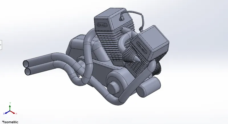
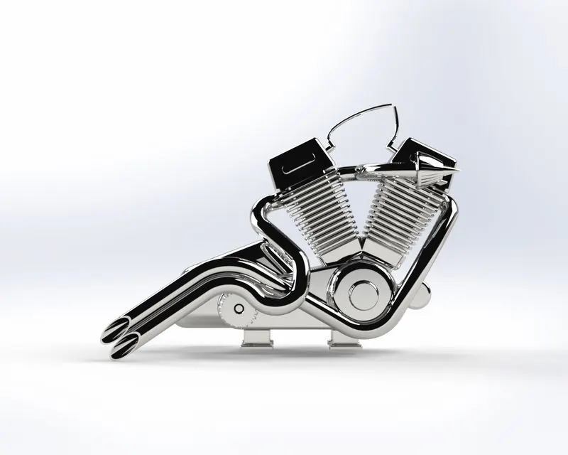
The engine was one of the most complex components to the model. A number of tools and features were used to model the engine. It is a twin-cylinder v engine. Even Though it is a cosmetic model it was modeled in such a way that it appears to be realistic when rendered images and produced.
Features used
- Convert entities
- Project curve
- Trim entities
- Circular pattern
- Split
- Dome
- Composite curves
- Projected curve
- Extrude boss
- Fillet
- Combine
- Appearance
- Gas tank
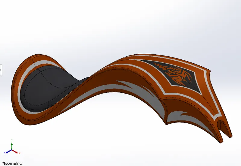
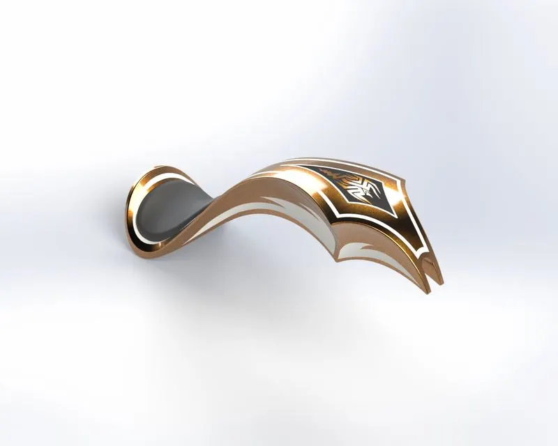
A number of splines, curves, and projected curves were used to model the gas tank. Decals were inserted to complete the appearance of the model. New tools like knit surface and loft surface were used to model the gas tank.
Features used
- Projected curve
- Trim entities
- Sweep boss
- Loft surface
- Knit surface
- Sweep cut
- Fillet
- Appearance
Assembled American chopper
The American chopper was assembled by using a variety of mate options available in the assembly workbench. The mate options used for the assembly are as mentioned below.
- Coincident mate
- Concentric mate
- Distance mate
- Parallel mate
- Tangent mate
- Width mate
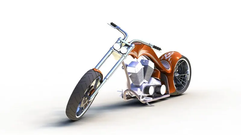
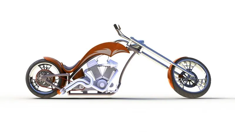
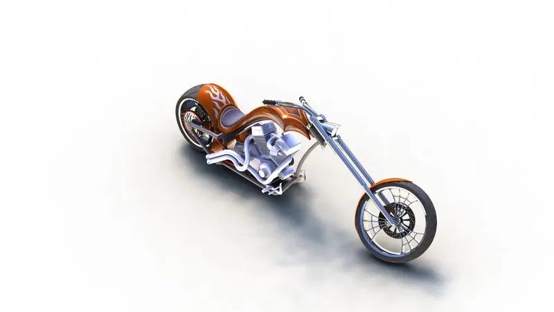
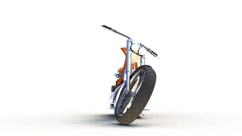
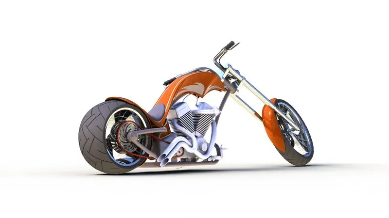
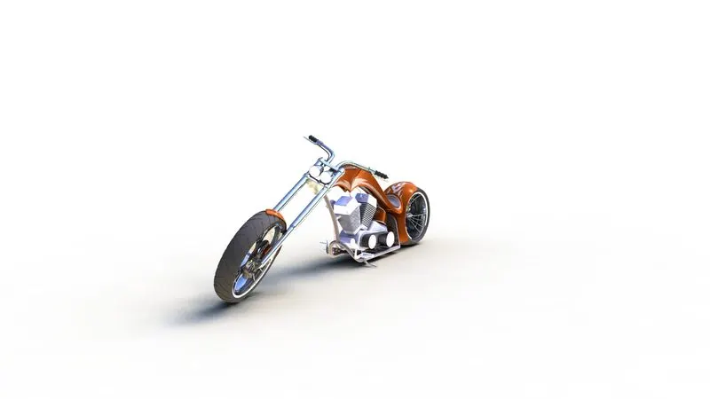
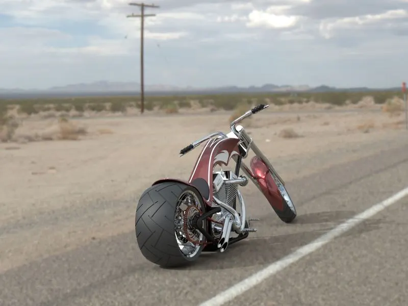
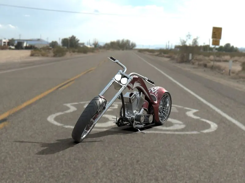
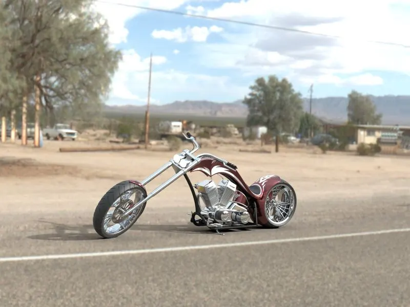
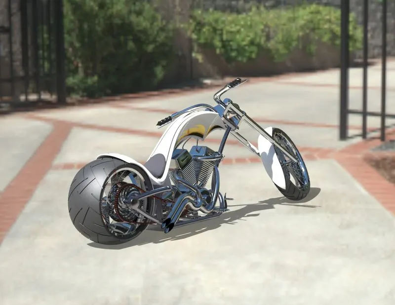
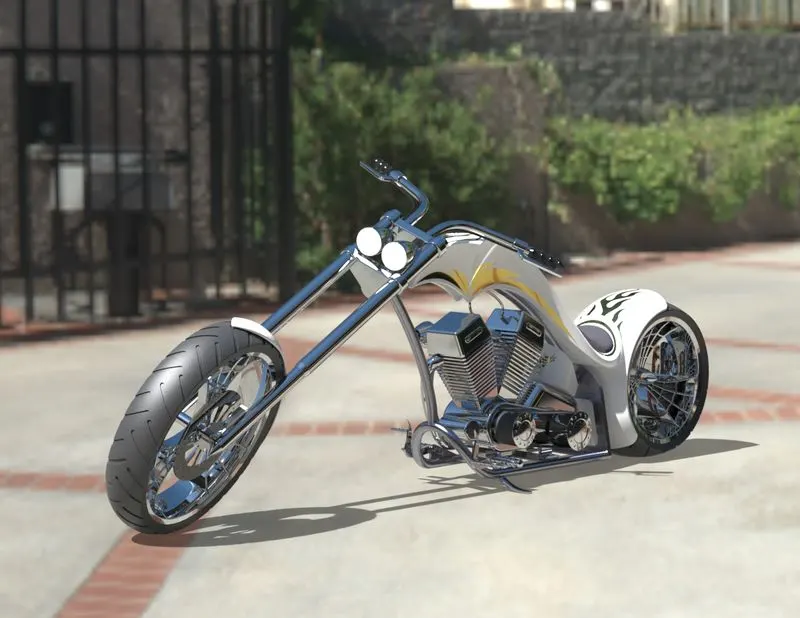
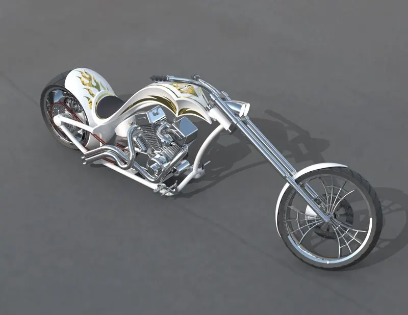
The renders of the American chopper created using Photoview 360 are shown below.
Renders created using SOLIDWORKS Visualize
CONCLUSION
An American Chopper was designed, modeled, and assembled using SOLIDWORKS 2022. Photo-realistic renders of the chopper were created using Photoview 360 and SOLIDWORKS Visualize 2022.