Week 8 - Challenge 2 - Switch Bezel Design
AIM:- Create the Switch Bezel Plastic component through the given Class-A surface. To begin with, the tooling axis for the given Class-A Surface should be created meeting the requirements of the draft angle and at the end perform the Draft analysis on the model.
Take the Thickness of the component to be 2.5 mm
Switch Bezel Design
Objective:
- To design switch bezel as per automotive OEM Standard.
- Create B Class and C Class and tooling axis.
- Converting close surface into the solid inside part workbench and provide the thickness of 2.5mm.
- Performing draft analysis to verify the creation of the Tooling axis and C Class surface.
Software:
- CATIA V5
Abstract:
In this project, I design a Switch Bezel using Catia v5. I received input as Class A Surface. I check the direction to eject the tool based on the component design. Later I checked whether all faces that intersected will clear the direction based on the tooling axis. I started working on the Draft Analysis tool to check if our tooling direction clears the path for easy removal of material from the tool. After that, I go class B creation using Advance tools from the surface followed by class C creation using the sweep command. After design A B C class surface, converting close surface into solid inside the part workbench.
Tooling axis creation
The tooling axis is the direction of drawing a sheet metal where the finished component is easily ejected on a particular direction and axis. The tooling axis is important for removing the material when finished.
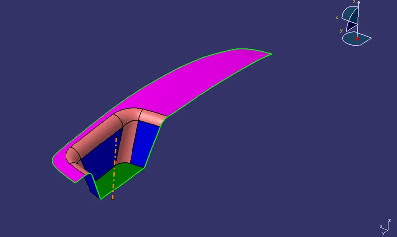
TOOLING DIRECTION
Creation of tooling Axis (Bisecting method)
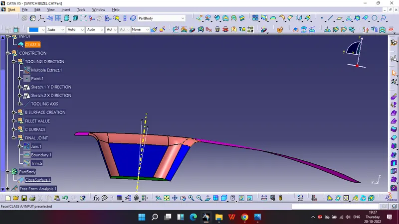
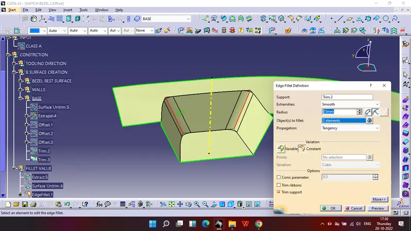
Creation of Class - B and Class - C surfaceE
extracting the class - A surface without the fillets and then untriming and extrapolateing them to join them, and after that offset the surface to 2.5 mm thickness which forms as the Class - B surface.
Class - C surface
By extracting the boundary of the class - A surface, the surface required for the class - C is obtained.
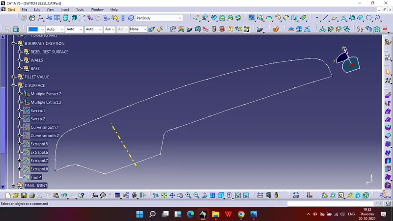
using the smooth curve option a smooth surface can be obtained by sweeping the line towards the direction of the tooling axis.
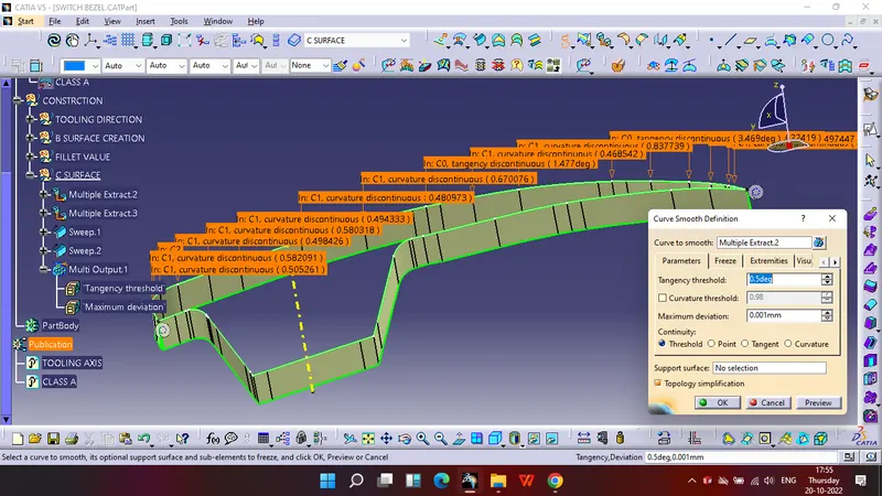
then using smooth surface
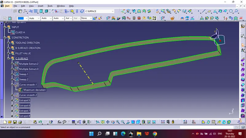
final output there
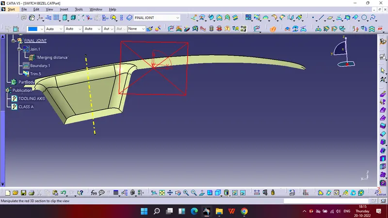
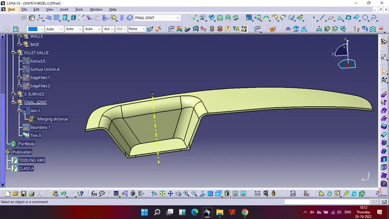
close surface body
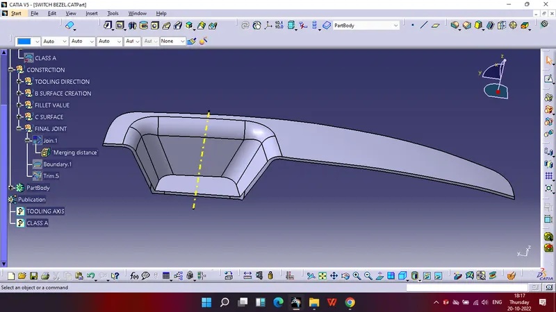
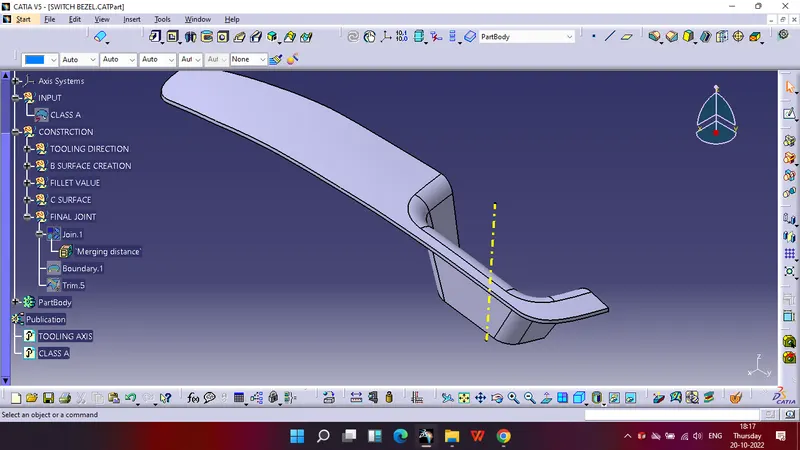
Draft Analysis
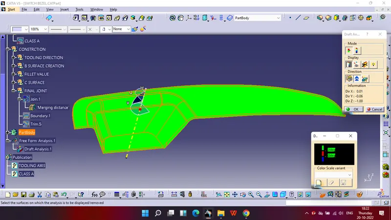
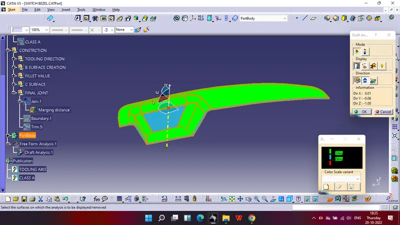
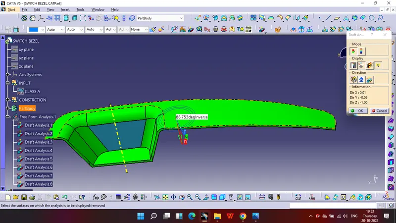
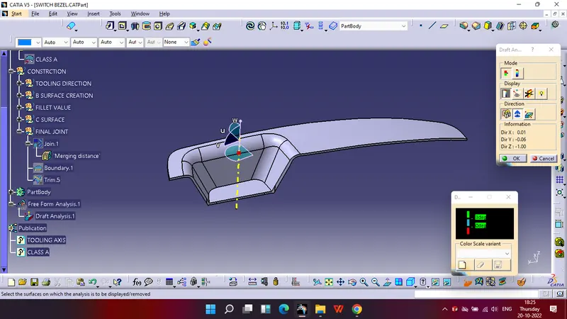
When a plastic component is made, we can observe that there is a draft angle given on each side from the base which is lesser than 90 degrees. This is because in the criteria of making a plastic material the mold should release the material when finished. if the mold surfaces are 90 degrees the material won't release from the mold because of friction due to contraction of material when cooled.
To resolve this problem we CAD engineers maintain a standard rule to design the plastic mold or die's in such a way that there is no problem while ejecting the plastic component. So a minimum of 3 - 10 degrees of draft angle is given to every plastic component while designing.