Week 8 - Challenge 2 - Switch Bezel Design
SWITCH BEZEL DESIGN
OBJECTIVE:
This Report objective is to design the switch bezel of a car as per Automotive OEM standards by defining tooling direction and creating class-B and class-C surfaces and to perform draft analysis with help of CATIA-V5.
PROCEDURE:
Checking the given Class-A surface:
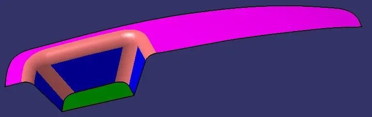
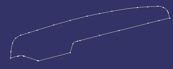
First, we need to check the given class-A surface using the Boundary command. If any errors or patches found, they need to be rectified.
Defining the tooling axis:
- Tooling axis is important for manufacturing any plastic component. It is the direction in which the plastic part is drawn after the completion of molding. So, it is important to have a good tooling direction.
- Generally direction normal to the flat surfaces/ holes in the component design is considered as the best tooling since it makes the whole operation easier and there by cost effective.
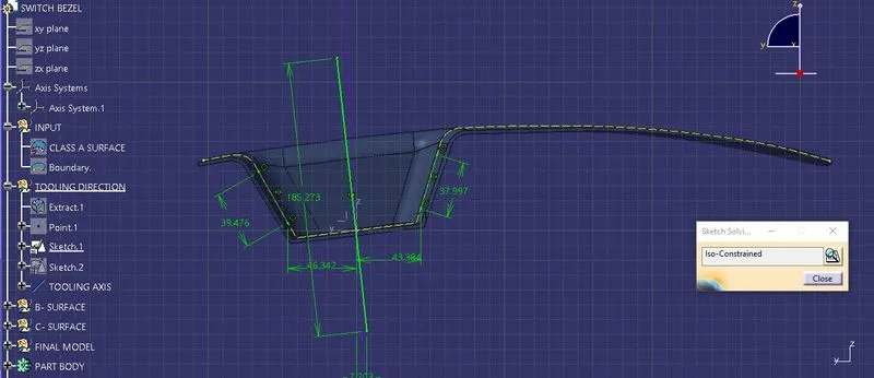
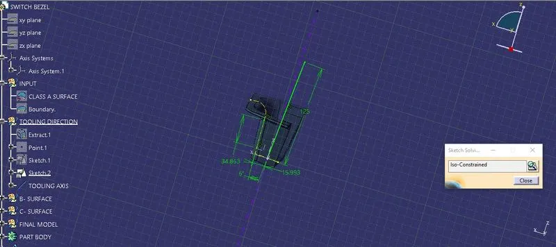
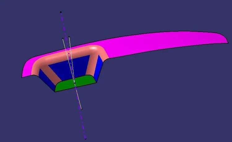
- In this case we take the initial tooling direction to be in the Z direction and then the surfaces which might create a problem with this direction are identified and the sketches for these surfaces are taken by assuming the tooling direction as the vertical axis for these sketch planes.
- The tooling direction with respect to the inclination of these surfaces is found by bisecting the lines which are derived from the inclined surfaces. Next the final tooling direction is found by bisecting the tooling directions obtained for the respective sketches.
Creation of Class-B surface:
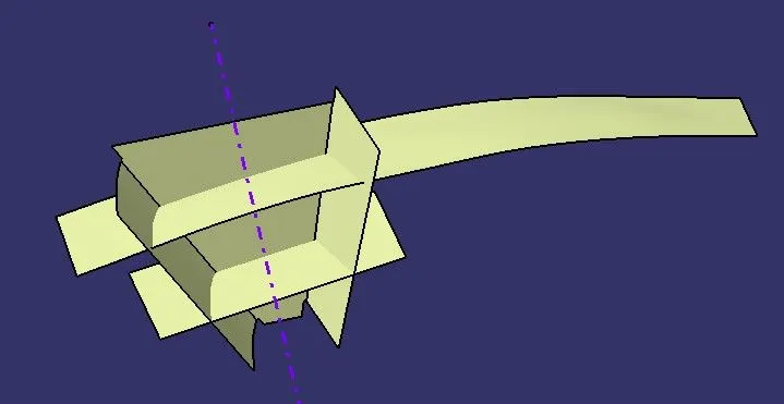
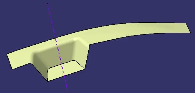
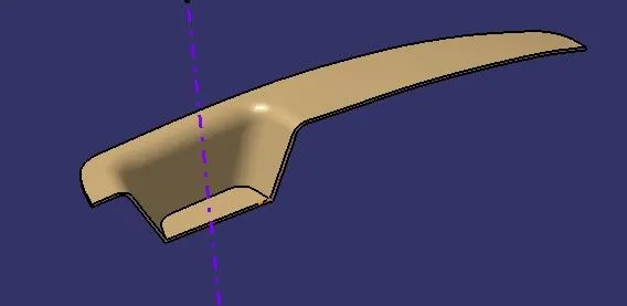
Class-A is the outermost surface of any body. The only purpose of class-A is to respect the dimensions and have good aesthetics while class-B is the innermost surface it contains all the necessary features that are necessary for the product to be functional and assembled. For the class-B surface, we cannot simply offset the whole class-A surface because of the errors that the fillets in the class-A might cause. So, first we are going to extract the faces excluding the fillets and the obtained faces are then untrimmed to get their original faces. These untrimmed faces are now extrapolated by the appropriate distance so that these surfaces are in contact with each other. Now the necessary parts are obtained by trimming these surfaces together. Now the obtained faces are offsetted by the given thickness value (in this case it is 3mm) and the final trims are applied to obtain the final B-surface.
Creation of class-C surface:
Class-C is the surface which joins the A and B-surfaces together. Now we use the boundaries of the class -A to obtain the C-surface. We use the sweep command and create a C-surface with a draft angle of 3 degrees with respect to the Final tooling axis that we obtained earlier. Now the Class-A and Class-C surfaces are joined together by following appropriate measures. The joined surfaces are trimmed with the class-B surface that we have and the final surface model is obtained.
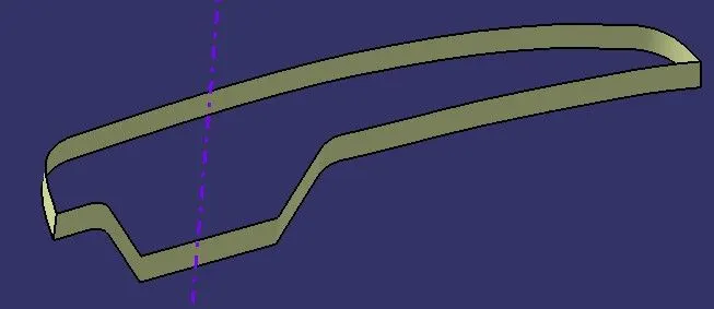
Surface Model:
Closed Body:
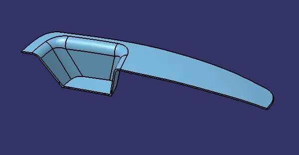
Now the model that we obtained using the surface workbench is converted into a solid body by using the closed surface command in the part workbench of CATIA-V5.
Draft analysis:
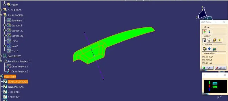
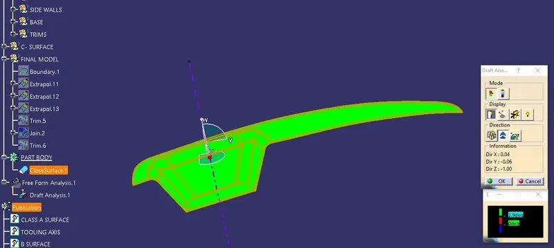
The final operation which is draft analysis is performed on the final model which we obtained in the previous step with respect to the final tooling direction obtained earlier and the results are visualized. If there are any surfaces with a draft angle less than 3 degrees it has to be corrected. In this case we are not allowed to modify the class-A surface so we need to change the tooling direction for the component so that all surfaces satisfy the minimum draft angle.
Class A surafce
Closed Body
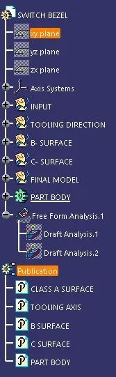
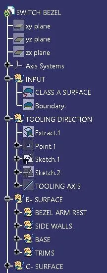
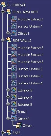
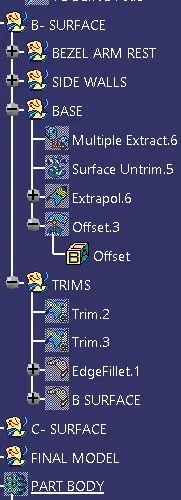
Detailed Tree structure
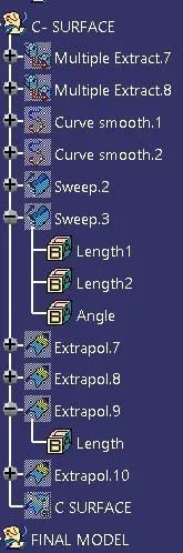
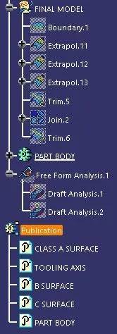
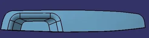
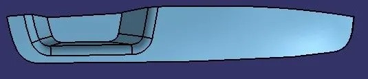
Different views of Final Closed Body
Isometric view
Front view
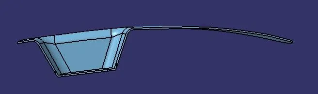
Side view
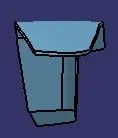
Top and bottom views
CONCLUSION:
Finally the Switch Bezel is designed with the help of Class A surface by defining tooling direction and creating Class B and C surafces. And the draft analysis resluts show that the component can be manufacturable with the help of Injection Molding processes.