Week 8 - Challenge 2 - Switch Bezel Design
Aim - Create the Switch Bezel Plastic component through the given Class-A surface. To begin with, the tooling axis for the given Class-A Surface should be created meeting the requirements of the draft angle and at the end perform the Draft analysis on the model.
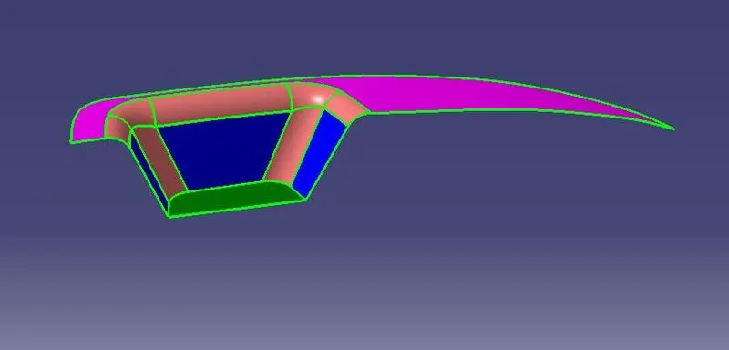
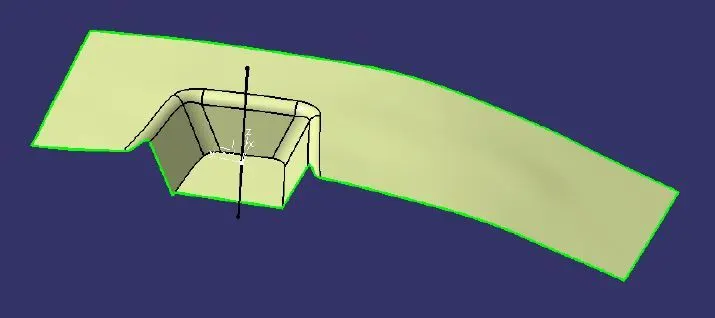
Given CLASS A SURFACE-
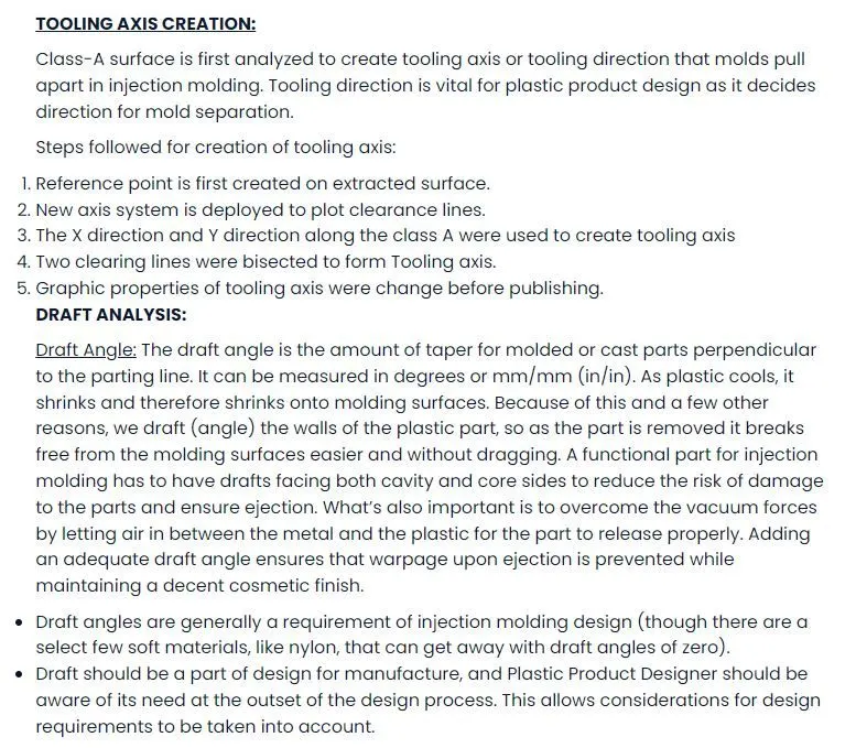
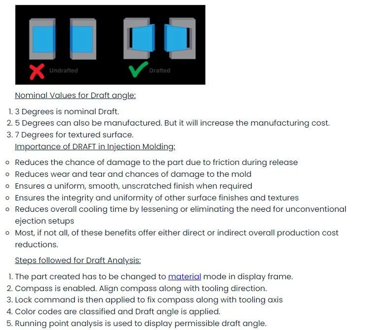
Report on draft analysis-
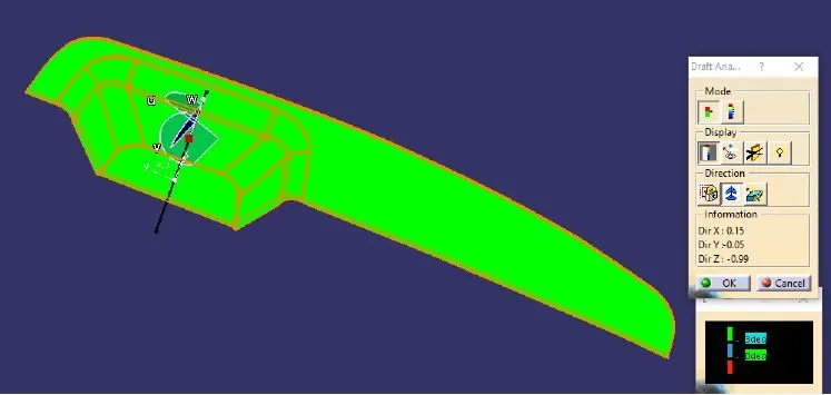
Explanation on Bisecting method-
Bisecting method is basically used to find the proper tooling axis using the dummy tooling axis. In Bisecting method bisecting line is used in which either bisect the two line or it will show error which means two lines are parallel to each other. We create tooling clearing axis for x and y which will be used to create the main tooling axis using the bisecting line option in the line command.
Class B Surface Creation:
• Extract the relevant surfaces from Class-A surface which excludes the Fillets and holes.
• Here the selected faces consist of Bezel Arm rest surface, Walls and the Base surface.
• Extract of these surfaces .
• Use Untrim Command to untrim the extracted surfaces and create a natural extend.
• Extrapolate the untrimmed surfaces so that each of them intersects clearly and pass way forward than the Class A which will help in its trimming in further operations.
• Offset the extrapolated surfaces to the value of required Thickness of the Part. In this case of Switch Bezel, the thickness value is 2.5 mm. The offset faces are the part of B-Surface.
• Create Fillets while maintaining the part thickness between the Class A and Class B surfaces. The Value of Fillet is given by the equation (B surface fillet = A surface fillet ` Thickness of the Part). The sign + or – must be decided so as to maintain the part thickness which in this case is 2.5mm.
Class C Surface Creation:
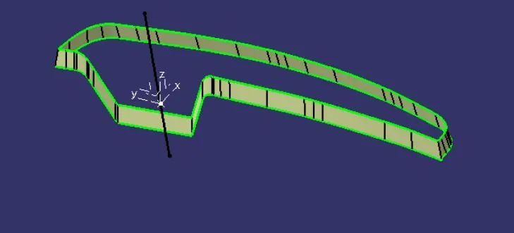
• Use Multiple Extract to extract the outer boundary of the Switch Bezel Class A surface.
• Use Smooth Curve since the multiple extract creates multiple sections
• Use Sweep Operation to extrude the boundary using the Draft direction option and selecting the Tooling Axis as the direction.
• Use draft angle as 3º and select outward direction arrow.
• Sweep it well beyond the B surface
• Use similar Sweep for other Smooth curve and if any gaps are found extrapolate and trim to make an enclosed surface.
Final Closed Surface Creation:
• Join all the Swept surfaces along with the Class A Surface.
• In this case gaps occur while joining so use 0.003mm.
• Even this method doesn’t fill up the gap so extrapolate Class A to about only 0.5mm and trim it off with C surface.
• The Final trim should be one single Surface Entity without any gaps
• Trim the Final Trim Surface with the Class B surface to obtain the final enclosed Surface for the Switch Bezel .
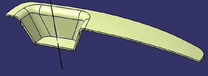
Conclusion- All the objectives have been achieved and CATpart file is also uploaded as a zip file.