Week 8 - Challenge 2 - Switch Bezel Design
AIM -
To design a solid switch bezel plastic part from the given Class A surface and to perform feature draft analysis on the provided Class A surface and the final solid part using CATIA V5.
TOOLS USED -
CATIA V5
DESIGN CONSTRAINTS -
- The provided class A surface should not be altered.
- A proper tooling axis must be created using the bisecting method.
- The draft allowance/draft angle for the generated A, B & C surfaces should be greater than or equal to 3 degrees.
- The thickness of the plastic component must not exceed 2.5mm and should be uniform for the entire part.
- The Close surface feature must be used to develop a solid body from the final surface.
- Proper publications of class A, B & C surfaces and tooling axis must be done respectively.
THEORY -
CLASS A SURFACE - Class A surfaces are freeform styling surfaces that have high quality and efficiency and are visually appealing without any kinds of manufacturing marks. These are the surfaces that the user can see, touch and feel.
CLASS B SURFACE - Class B surfaces are the surfaces in a component that carry all the engineering features or attachment features. These are not at all visually aesthetic and appealing. These surfaces are oppositely positioned to a Class-A surface.
CLASS C SURFACE - Class C surface is what connects the Class-A and Class-B surfaces together. It is a connecting surface that closes the component during design. Class C Surface is where a designer applies a draft which should always be greater than equal to 3 degrees in case of a plastic part, for it to be manufactured properly.
TOOLING AXIS - It is an imaginary axis along which the core and cavity of the mold will move in order to manufacture the plastic component.
CREATION OF TOOLING AXIS - BISECTING METHOD -
A tooling axis is a direction along which the core and cavity would move along while manufacturing the plastic component in real life. The tooling axis must be so created such that, the finished plastic component maintains a minimum of a 3-degree draft on all its surfaces so that it is easily exited from the mold without having to face any defects.
The method used for creating a tooling axis, in this case, was the bisecting method.
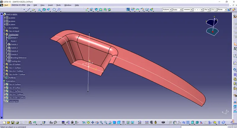
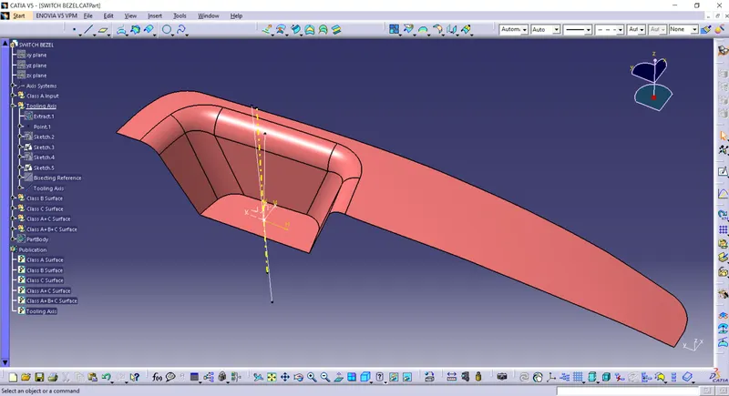
For creating the first reference tooling axis, firstly an intersection of the given class A surface is taken along the Y-Z plane of a newly created axis system. This new axis system was generated by creating a point at the centre of an extract of the base surface of the given class A surface and using it as a reference. This intersection was used as a reference for creating the first reference tooling line using the bisecting line feature as shown in the figure.
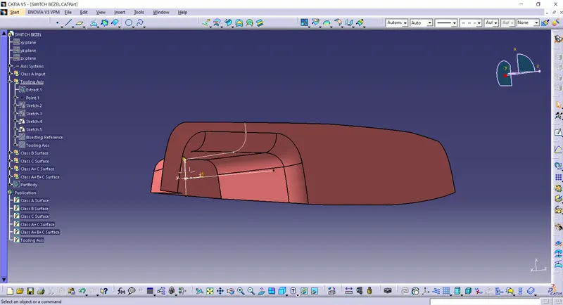
For creating the second reference tooling axis, an intersection of the given class A surface is taken along the X-Z plane, again with respect to the previously created axis system. Due to a lack of a sufficient number of surfaces in this direction, a line is drawn maintaining an inclination that is greater than or equal to the required draft of 3 degrees as shown in the figure, which will be used as the second tooling line.
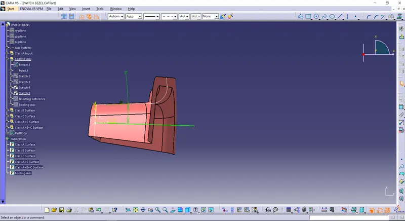
Now, A bisecting line is again created by taking the first reference tooling axis and the second reference tooling axis as its reference. This line serves as the final tooling axis for the plastic component.
DRAFT ANALYSIS EXPLANATION -
The draft analysis enables the designer to verify if the designed part is following a proper draft angle on its surfaces wherever necessary. It provides the user with a clear colour-coded picture of the developed part which helps in understanding where the part is failing to follow the draft. It tells us if the part we designed is manufacturable.
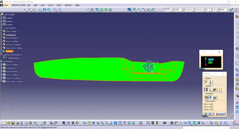
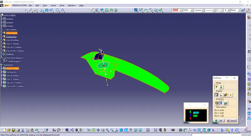
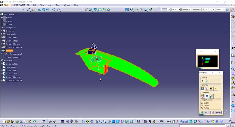
A complete feature draft analysis was performed for the given Class-A surface, as well as the finished solid plastic part. While performing the draft analysis, the compass direction must always coincide with the direction of the tooling axis. Once coincided, when we select the part or the surface, a colour-coded representation of the respective part and the surface are displayed as shown in the figure. The draft angle and its respective colour can be adjusted according to the designer's requirement.
Here, both the given Class-A surface and the final solid part turned out to be green for a selected angle of 3 degrees which tells us that the part can be manufactured without any problem.
Draft Analysis of Class-A Surface -
Draft Analysis of Final Plastic Part in Different Views -
Isometric View
Front View
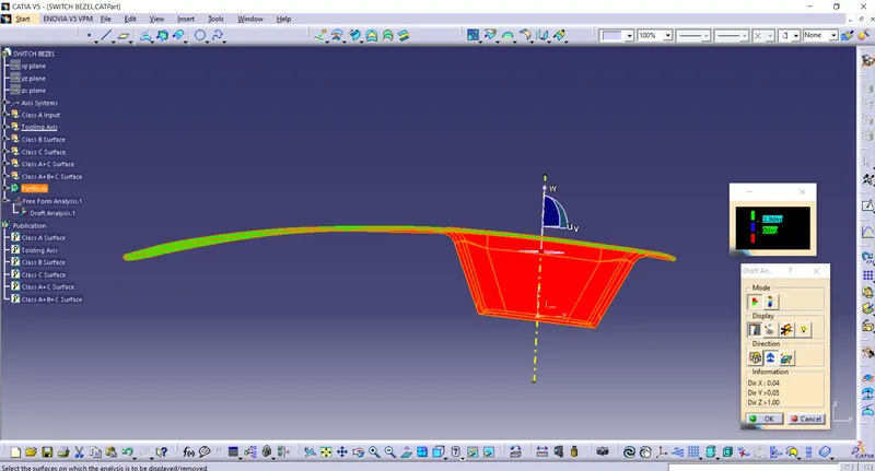
Right View
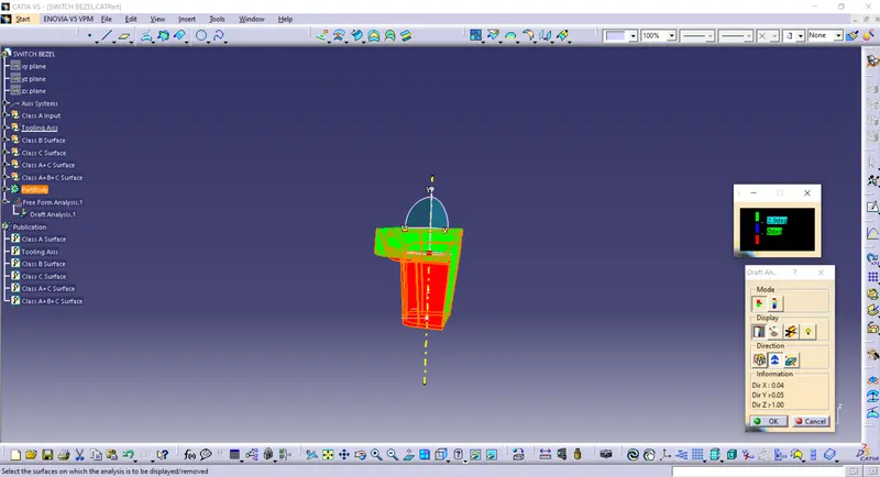
Top View