Week 8 - Challenge 2 - Switch Bezel Design
Draft angle: The degree of taper of the side wall of the mold or the angle of clearance designed to aid the removal of a part from a mold.
Most of the parts have a draft angle of min 3, but while designing we follow the general thumb rule of 1-degree draft per 1-inch depth.
Draft angle is provided along the TOOLING AXIS.
Tooling Axis: It is the direction in which the core and cavity of the mold move for the removal of the component inside it.
Creation of Tooling Axis:
- First, inspect the given CLASS A surface. Use the join feature to check whether the surface has a continuous boundary or not.
- Then check the direction in which the component can be easily molded without any complications.
- After finding the correct direction cut the surface using a plane or axis system to generate curves.
- By inspecting the curves, select the curves that are inclined to the dummy axis we have created.
- Create lines along the surfaces and bisect them to get a bisector.
- Create another line at an angle to the surface and bisect it with the previous bisector line to get real TOOLING AXIS.
- I have created the Tooling axis by bisector method but my part hasn't cleared draft analysis.
- Then I checked using TOOLING AXIS as normal to the surface, and it cleared the draft analysis.
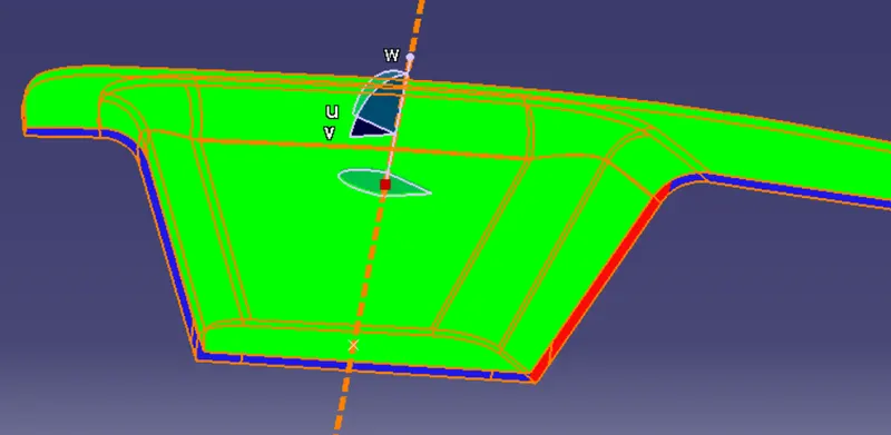
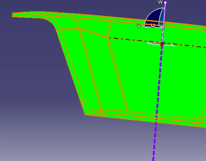
Draft Analysis Using Tooling Axis:
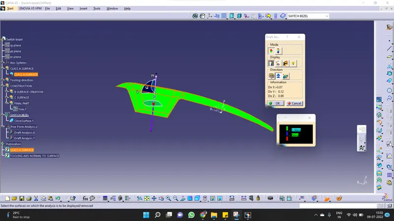
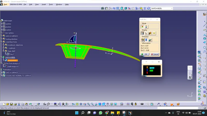
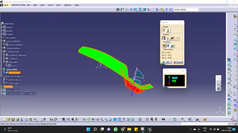
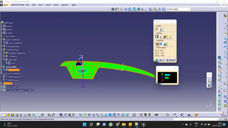
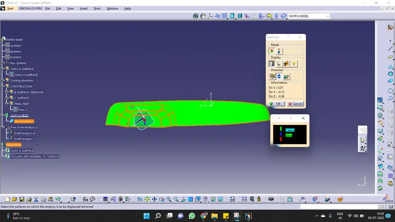
- After generating the Tooling Axis of the given CLASS A surface, insert the feature draft analysis from the analysis toolbox.
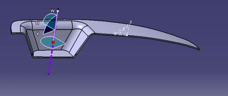
- Drag the axis system and try to align along the Tooling Axis.
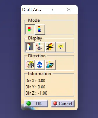
- We observe the Draft analysis box that contains the mode, display, direction, and information of the tooling axis.
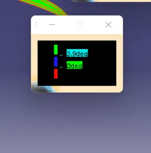
- Using the Draft analysis box complete draft analysis is performed and different draft angles are coded in different colors.