Week 8 - Challenge 2 - Switch Bezel Design
CHALLENGE 22 – SWITCH BEZEL DESIGN & DRAFT ANALYSIS
Aim: Given Class A input surface, complete the thickened Switch Bezel part and perform draft analysis on the completed part.
CLASS A SURFACE
We were provided the Class A Surface as below.
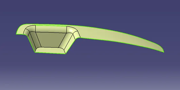
Fig 1 – Original Class A Surface before Translation
We then created two partial tooling directions, X and Y. These were created in Sketches 1 and 2 by bisecting lines derived from the intersection of the sketch plane with the Class A Surface. Finally, we bisected the two partial tooling lines to produce the final Tooling Axis.
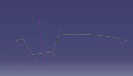
Fig 2 – Sketch 1 -- TOOLING X (Partial Tooling Direction Sketch)
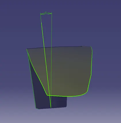
Fig 3 – Sketch 2 -- TOOLING Y (Partial Tooling Direction Sketch)
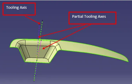
Fig 4 – Final Tooling Axis (The Green Line Bisects the two Partial Tooling Lines)
Thickened Part
After creating the Tooling Axis, we created the Class B and Class C surfaces and trimmed them with the Class A surface. Finally, we used Close Surface to produce a final, thickened, solid part.
Feature Tree
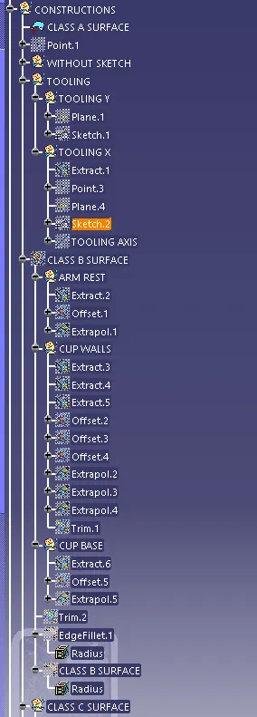
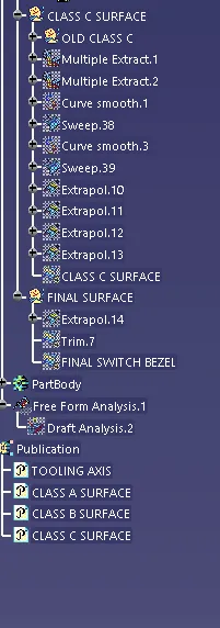
Fig 4 – Feature Tree
VIEWS
Below are four views of the final part (Iso, Front, Side, Top):
Iso
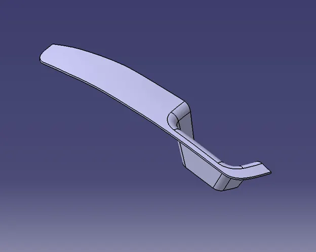
Fig 5a - Iso
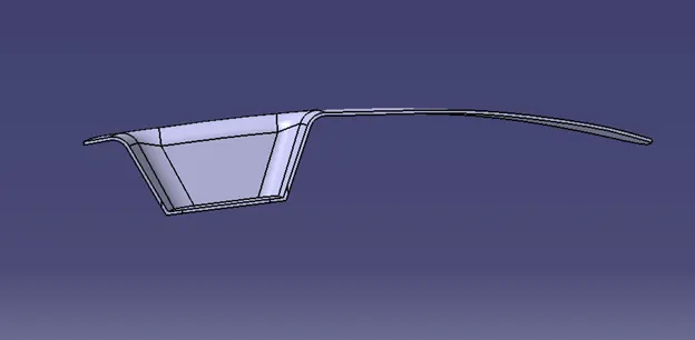
Fig 5b - Front
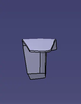
Fig 5c - Side
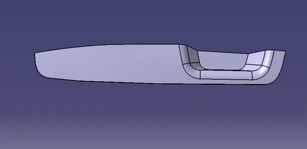
Fig 5d – Top
Draft Analysis
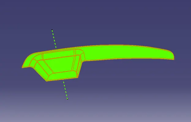
Fig 6 -- DRAFT ANALYSIS
The Draft Analysis validated the design for manufacturability.
Conclusion: We were able to successfully model the part and verified it for Draft Analysis.