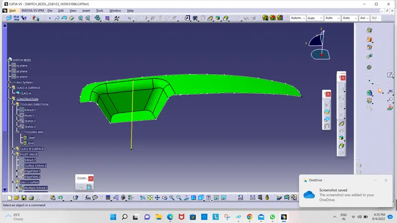
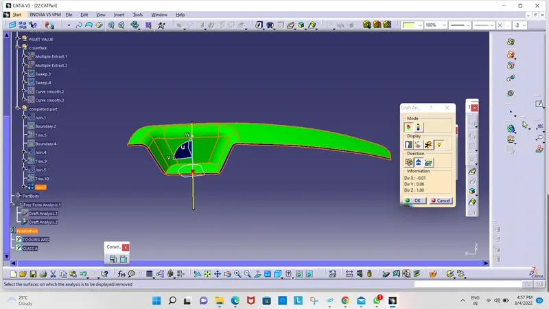
Week 8 - Challenge 2 - Switch Bezel Design
aim: Create the Switch Bezel Plastic component through the given Class-A surface. To begin with, the tooling axis for the given Class-A Surface should be created meeting the requirements of the draft angle and at the end perform the Draft analysis on the model.
Objective :
- To design switch bezel as per automotive OEM Standard.
- Create B Class and C Class and tooling axis.
- Converting close surface into the solid inside part workbench and provide the thickness of 2.5mm.
- Performing draft analysis to verify the creation of the Tooling axis and C Class surface.
Software :
- CATIA V5 (Generative Shape Design)
Abstract:
In this project, I design a Switch Bezel using Catia v5. I received input as Class A Surface. I Check the direction to eject the tool based on the component design. Later I checked whether all faces that intersected will clear the direction based on the tooling axis. I started working on the Draft Analysis tool to check if our tooling direction clears the path for easy removal of material from the tool. After that, I go class B creation using Advance tools from the surface followed by class C creation using the sweep command. after design A B C class surface, converting close surface into solid inside the part workbench.
Design Methodology with images:
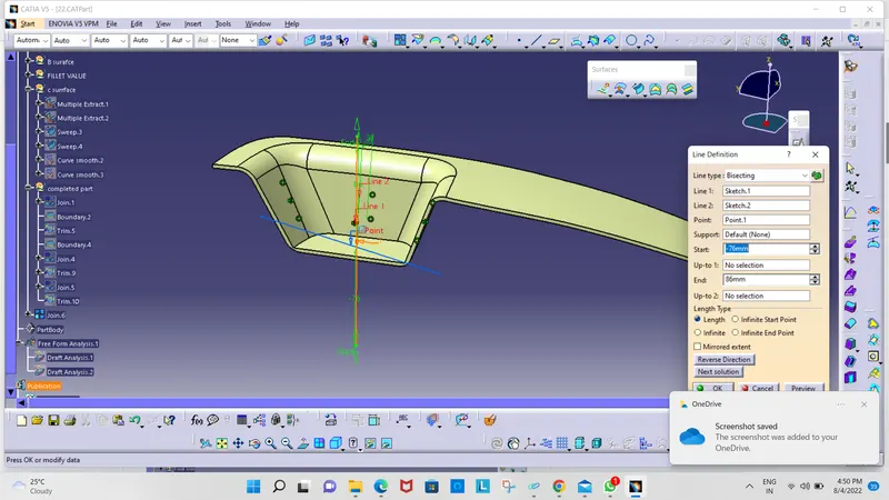
Procedure for creating Tooling Axis
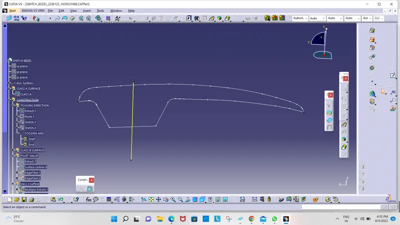
- A Reference Point is created along the Surface zero and a new Axis system is created
- The X Direction along Class A and Y direction along Class A were used to create the Tooling direction
- Finally, the Tooling axis is created by bisecting the two lines and it is published. Class A Surface as input using surface operation commands Class B is developed
- The tooling Axis determines the direction of the Class C boundary swept with draft direction.
- When viewing from the tooling direction normal all the parts that are drafted should be visible so it gives a rough idea to determine product manufacturing in Injection molding.
Procedure for B Surface Creation
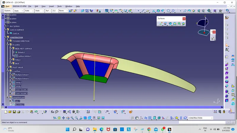
- The next step is to design the B surface for the input which is usually the surface where all engineering aspects and support creations are done.
- The B surface Creation is performed using surface operations in CATIA which is an offset from Class A with dimension proportional to the thickness of the part
- In the Switch bezel, the B surface is offset 2.5mm from the input which is the thickness of the part
- The B surface is an extrapolated surface compared to the A surface and forms the bottom skin of the part.
Procedure for C Surface Creation
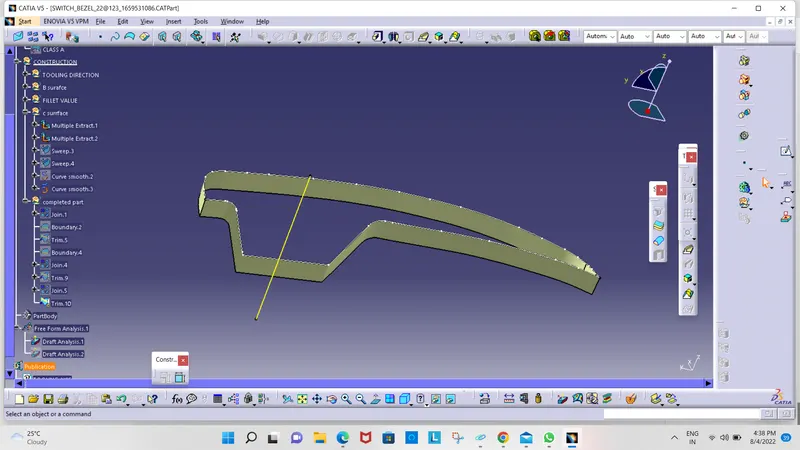
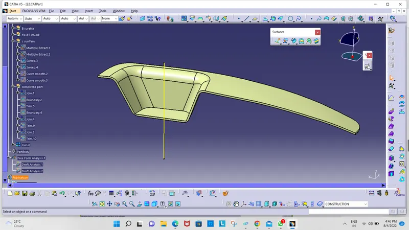
- The Next step is to form the C surface which is an intermediate surface between A and B and is used to give the closed surface appearance to the design
- The C Surface is swept using the profile as the boundary line of Class A which is the Guide curve with a subtype along the draft direction.
- The Direction of the sweep is the tooling direction formed earlier
- The draft angle for the sweep operation is provided which is 3 Degree and the surface is swept for length above the thickness of the specified part
- The C surface is refined using smooth Curve options to remove the complexity and patches along the swept surface
- Finally, the Class A and Class C surfaces are joined together and the connexity of surfaces should be less than 0.003mm, and the surfaces are merged.
Procedure for Closed Body Creation
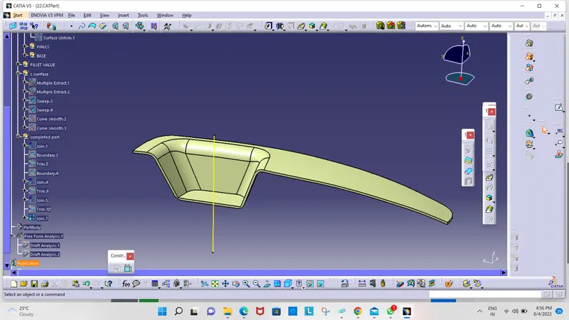
- The merged surface is then trimmed with a B surface to form the closed surface.
- The Closed surface is then validated to find the irregularities along the edges and imperfections along the edges were then corrected using operations like extrapolate and surface trim
- This Closed surface is the outer skin of the switch bezel and finally, the part is formed by the Closed Surface in the part design workbench
- The final part is measured to validate the uniform thickness of the part, especially along the filleted edges.
Procedure for Draft Analysis Procedure
- The part created has to be changed to the material mode in the display frame
- Then by enabling compass definition the axis system is pan along the direction of the part and aligned in line with the tooling direction
- Lock Direction is applied that fixes the compass and then the mode dialog box is formed by snapping at any point on the part
- The Color Codes are classified and Draft Angle are applied
- Then the Running point analysis is used to hover around the part to analyze the permissible draft angles and the analysis is saved