Week -2
- AIM: -
Make a Simulink model of doorbell using a solenoid block and use a thermistor to sense the temperature of a heater & turn on or turn off the fan.
- OBJECTIVE: -
2.1 Make a Simulink model of a Doorbell using a solenoid block with the following details;
Create a situation where the switch is closed for 2 seconds and then released. Observe the physical movement of the plunger.
2.2 Use a thermistor to sense the temperature of a heater & turn on or turn off the fan as per the below conditions:
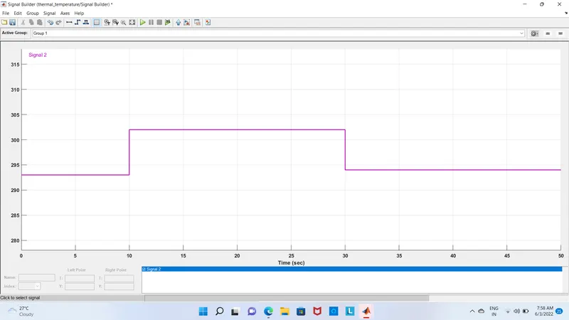
Temperature source: 20 °C from 0 to 10 seconds, 27 °C from 10 to 30 seconds, and 23 °C from 30 to 50 seconds. Fan conditions: ON if the temperature is above 25 °C, OFF otherwise
- OBJECTIVE 1
- Doorbell: -
The most widely used form is the interrupter bell, which is a mechanical bell that produces a continuous sound when current is applied. The bell (B), which is often in the shape of a cup or half-sphere, is struck by a spring-loaded arm (A) with a metal ball at the end called a clapper, actuated by a solenoid (E). In its rest position, the clapper is held away from the bell a short distance by its springy arm. When the switch (K) is closed, an electric current pass from the battery (U) through the winding of the solenoid. It creates a magnetic field that attracts the iron arm of the clapper, pulling it over to give the bell a tap. This opens a pair of electric contact (T) attached to the clapper arm, interrupting the current to the solenoid. The magnetic field of the electromagnet collapses, and the clapper springs away from the bell. This closes the contacts again, allowing the current to flow to the solenoid again, so the magnet pulls the clapper over to strike the bell again. This cycle repeats rapidly, many times per second, resulting in a continuous ringing.
The tone of the sound generated depends on the shape and size of the bell resonator. Where several bells are installed together, they may be given distinctive rings by using different size or shapes of bell, even though the strike mechanisms are identical.
Another type, the single-stroke bell, has no interrupting contacts. The hammer strikes the gong once each time the circuit is closed. These are used to signal brief notifications, such as a shop door opening for a customer, rather than continuous warnings.
- Solenoid: -
A solenoid is a device comprised of a coil of wire, housing and a moveable plunger (armature). When an electrical current is introduced, a magnetic field forms around the coil which draws the plunger in. More simply, a solenoid converts electrical energy into mechanical work. The coil is made of many turns of tightly wound copper wire. When an electrical current flows through this wire, a strong magnetic field/flux is created.
The housing, usually made of iron or steel, surrounds the coil concentrating the magnetic field generated by the coil. A solenoid is a device comprised of a coil of wire, housing and a moveable plunger (armature). When an electrical current is introduced, a magnetic field forms around the coil which draws the plunger in. More simply, a solenoid converts electrical energy into mechanical work. The plunger is attracted to the stop through the concentration of the magnetic field providing the mechanical force to do work.
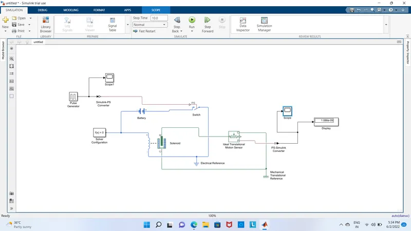
3.1 SIMULINK MODEL: 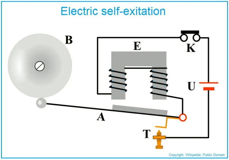
3.2 BLOCKS USED: -
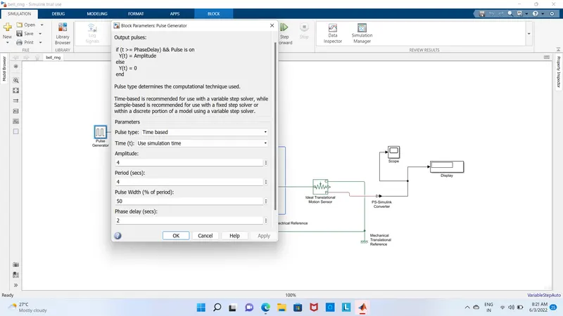
- Pulse Generator: - The Pulse Generator block generates square wave pulses at regular intervals. The block waveform parameters, Amplitude, Pulse Width, Period, and Phase delay, determine the shape of the output waveform.
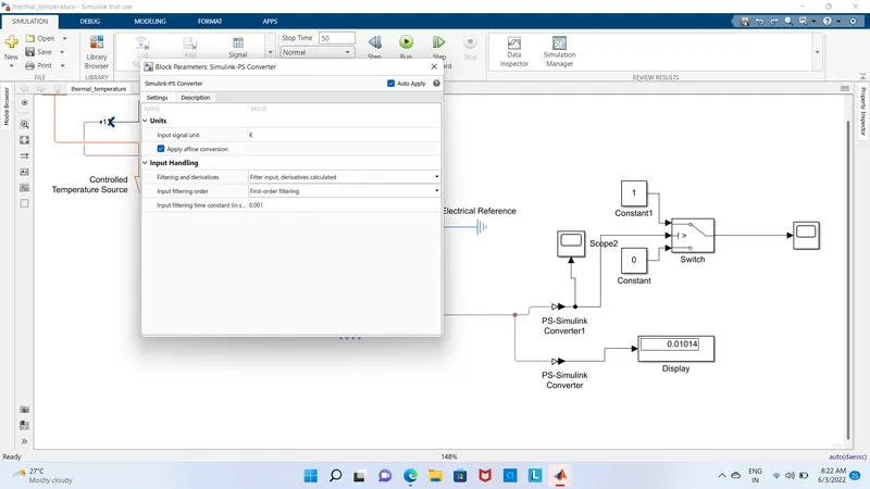
- Simulink-PS Converter: - The Simulink-PS Converter block converts the input Simulink signal into a physical signal. Use this block to connect Simulink sources or other Simulink blocks to the inputs of a Simscape physical network.
- Switch: - The Switch block models a switch controlled by an external physical signal. If the external physical signal PS is greater than the value specified in the Threshold parameter, then the switch is closed, otherwise, the switch is open.
- Battery: - The Battery block implements a generic dynamic model that represents the most popular types of rechargeable batteries.
- Solenoid: - The Solenoid block represents the electrical characteristics and generated force for the solenoid
- Solver Configuration: - Each physical network represented by a connected Simscape block diagram requires solver settings information for simulation. The Solver Configuration block specifies the solver parameters that your model needs before you can begin the simulation.
- Ideal Translation Motion Sensor: - The Ideal Translational Motion Sensor block represents a device that converts an across variable measured between two mechanical translational nodes into a control signal proportional to velocity or position.
- Scope: - Display signals generated during simulation.in simple words display a graph with respect to time.
3.3 Explanation Model and Output: -
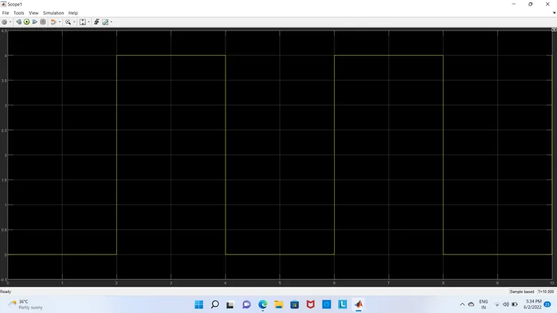
- Firstly, the pulse generator block is used to give signal inputs like amplitude, pulse width, period, and phase delay to determine the shape of the output length. The scope is used to see the graph of wavelength.
- After that Simulink-PS Converter is used to convert signal input to the physical system and send it to the switch block.
- To complete the circuit the battery, switch, and solenoid block are used and connect to each other. The electric reference is used as a ground. All systems are connected in series. The solver configuration block is used to specify the solver parameter.
- The mechanical part of the solenoid (clapper) is connected with the ideal translation motion sensor because the motion of the clapper is the translation and for the ground, the mechanical translation reference is used.
- The scope is connected to an ideal translation motion sensor to see the output graph of plunger motion. The output is as follows,
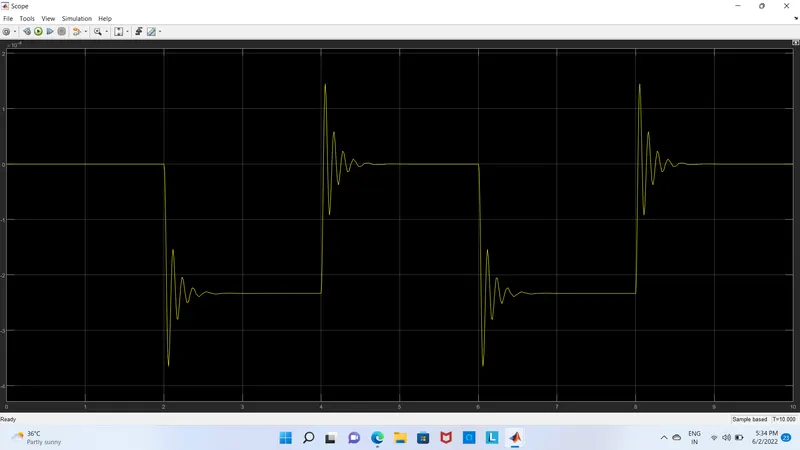
In the above graph we can see that the switch is closed for 2 sec after that switch is open. Amplitude is equal to 0 means the switch is closed. We can also see that the clapper strings every 2 seconds. The motion of the clapper is as we can see in I above graph with the help of scope.
3.4 CONCLUSION: -
We can conclude from the above output results that we have successfully simulated the doorbell mechanism operated by solenoid with given conditions as we can see in the above graph.
- OBJECTIVE 2
THERMISTOR: -
A thermistor (or thermal resistor) is defined as a type of resistor whose electrical resistance varies with changes in temperature. Although all resistors’ resistance will fluctuate slightly with temperature, a thermistor is particularly sensitive to temperature changes. The working principle of a thermistor is that its resistance is dependent on its temperature. We can measure the resistance of a thermistor using an ohmmeter.
There are two types of thermistors:
- Negative Temperature Coefficient (NTC) Thermistor
- Positive Temperature Coefficient (PTC) Thermistor
In an NTC thermistor, when the temperature increases, resistance decreases. And when temperature decreases, resistance increases. Hence in an NTC thermistor temperature and resistance are inversely proportional. This is the most common type of thermistor.
In a PTC thermistor the reverse relationship between temperature and resistance. When temperature increases, the resistance increases. And when temperature decreases, resistance decreases. Hence in a PTC thermistor temperature and resistance are inversely proportional. Although PTC thermistors are not as common as NTC thermistors, they are frequently used as a form of circuit protection. Similar to the function of fuses, PTC thermistors can act as current-limiting devices.
4.1 SIMULINK MODEL
 \
\
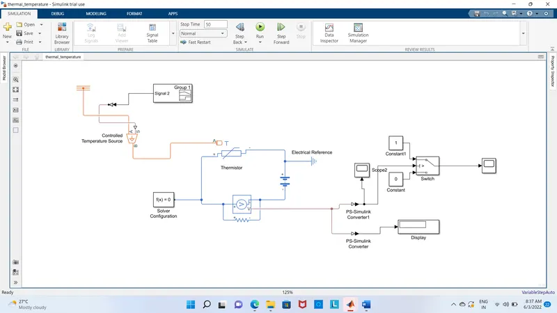
- The battery and voltage sensor are connected in series and the resistor is connected in parallel to the voltage sensor. The solver configuration is also used to specify the solver parameter. The electric reference is also used to ground the electric system.
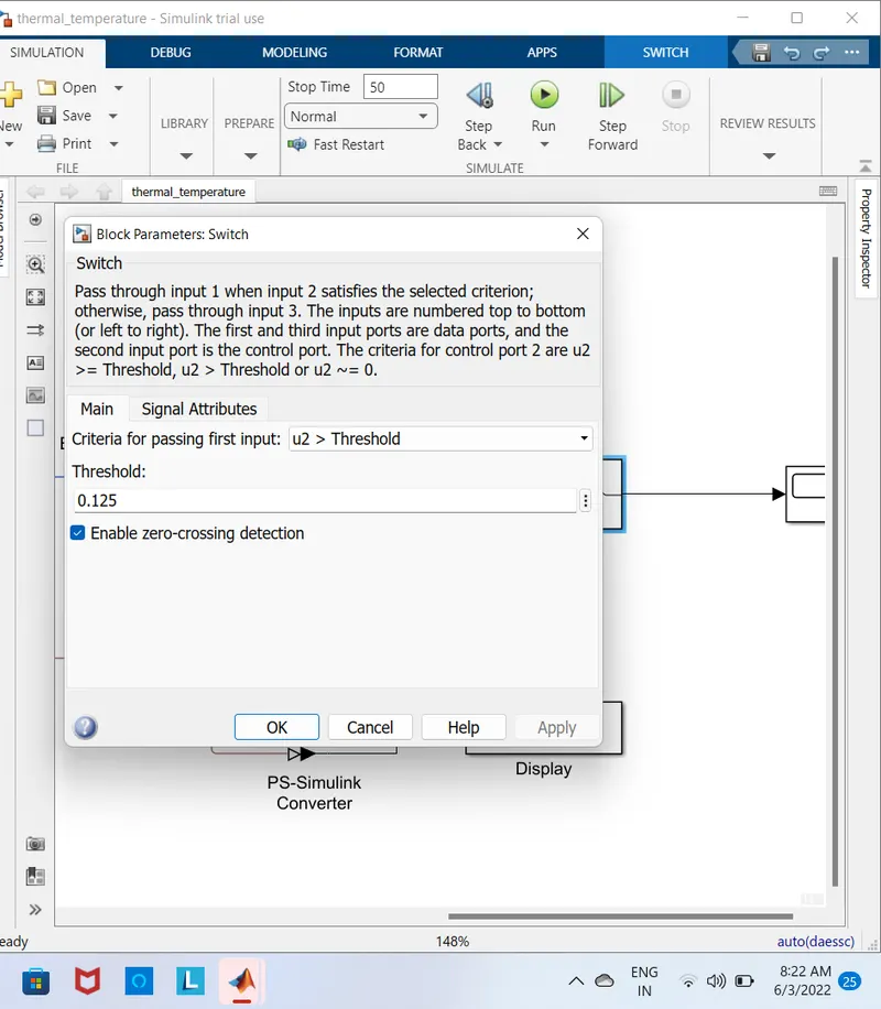
- The voltage sensor is connected to a switch to control the fan with the help of a PS-Simulink converter to convert the signal into Simulink input. After that, we use a scope to decide the threshold value of the switch. Also, we connected the display to show the last simulation value so we can decide our threshold value with the help of the PS- Simulink converter.
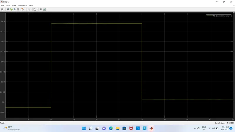
- In the switch decided threshold value. If the temperature is above the threshold limit, then it gave “1” as output which means fan switch on and if the temperature is below the threshold limit, then I gave “0” as output which means fan switch off.
8.
- At the end of the system, the scope is connected to see the output for fan on or off. We run the simulation for 50 sec because we take the time limit in signal builder as 50 sec. So, we can get the following output,
In the above graph, we can see form 0-10 sec signal is “0” because in this time the temperature was 20℃ which is below 25℃ means the fan is switched off. After that from 10-30 sec signal is “1” because at this time the temperature was 27℃ which is above 25℃ means the fan is switched on. At the end from 30-50 sec signal is “0” because at this time the temperature was 23℃ which is below 25℃ meaning fans were switched off.
5. Conclusion: -
We can conclude that from the above output results of our Simulink model for solenoid-operated heaters give correct output and satisfy all input conditions