Week 8 - Challenge 2 - Switch Bezel Design
AIM
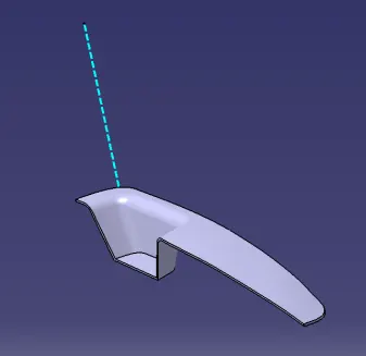
Create the Switch Bezel Plastic component through the given Class-A surface. To begin with, the tooling axis for the given Class-A Surface should be created meeting the requirements of the draft angle and at the end perform the Draft analysis on the model.
Take the Thickness of the component to be 2.5 mm
Report of draft analysis
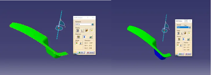
In a draft analysis we have to position the tool direction on surface class A and the compass should be lock in the tool direction and then check the analysis under running point should check the draft angel on the surface oh the class c
If the
red represent - no draft
Green represent - positive draft on cavity side
Blue represent - negative draft on core side
Please check the report in given below attached file for draft analysis
Procedure
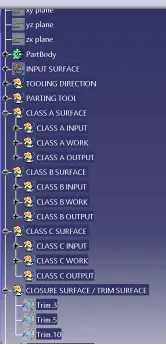
- If the geometrical set has divided as per guide
Tooling direction
We make a point & line in on the surface on the hole center for tooling direction
And the tooling direction depends upon the surface of draft angel given by as and then we move on the tooling direction
And the direction of compass should be an lock through the line along the surface
If the tooling direction to desired the cavity and core side of the surface
Surface A
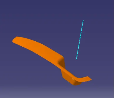
Repair the class a surface there is a n number of surface we should be the join the all surface together in single surface
Surface b operation
1st we start form the surface a and then offset 2.5mm from the class a toward the an z direction
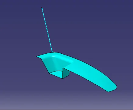
SURFACE C
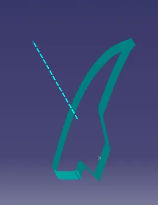
TRIM operation
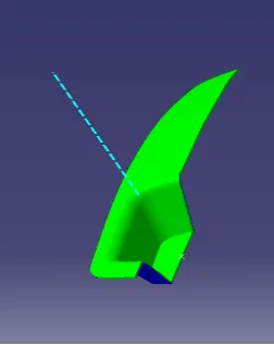
PARTING LINE
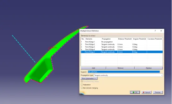
CLOSED SURFACE ON PART BODY