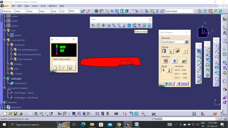
Week 8 - Challenge 2 - Switch Bezel Design
Draft Analysis
Draft Analysis is used to analyse whether given product model is manufacturable or not. There is at least some minimum Draft angle should given for each and every product, so that the mould and part making minimum point of contact when the ejection time. It also reduces the part getting affected by the mould.
Here is the complete list of steps involved in Draft analysis for given model.
Class A Surface:
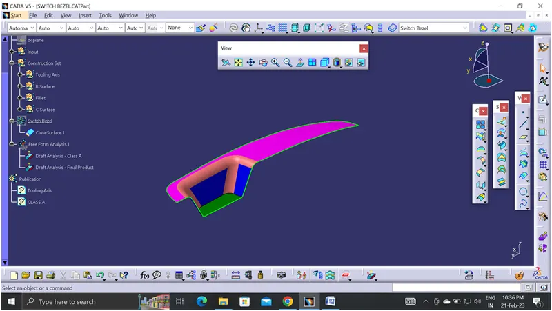
Procedure for creating draft analysis:
In the given class surface, have to check whether the given class a surface to clear the draft analysis, so that we have to decide whether the given product is manufacturable or not.
Creating a Tooling axis is mandatory for checking the draft analysis. On the reference of the Tooling axis only our draft analysis should perform. For creating tooling axis first analyse the given part in X, Y & Z view point and decide the maximum possibility to create the given part.
Step 1: checking the possibility of tooling axis in X, Y & Z direction.
In X – Direction, Maximum part should be producible but side wall not visible clearly.
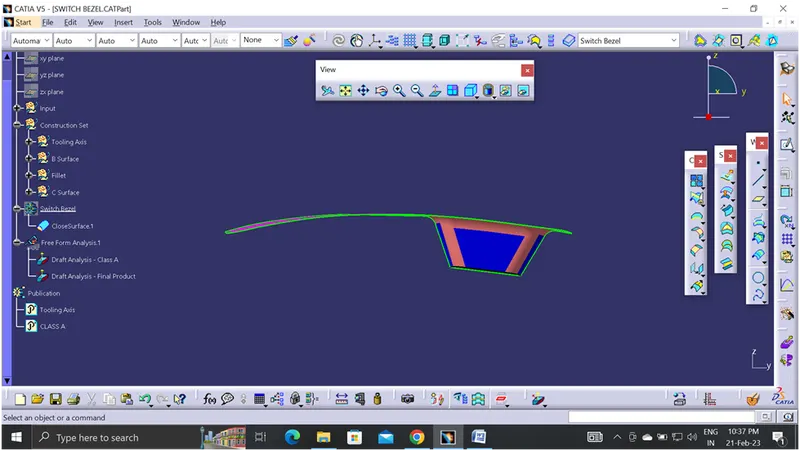
In Y – Direction, the part looks not a clear dimension so the part should not manufacture under this condition.
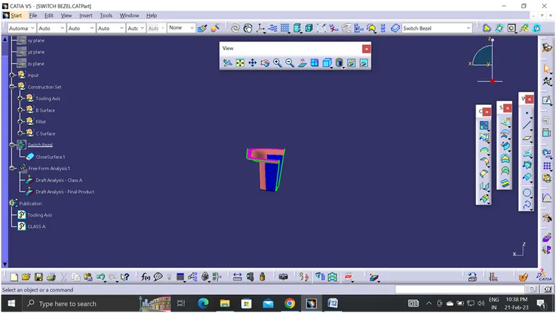
In Z- Direction, it's clear to see all the dimension and proper structure of the part.
Tooling Direction: "Z"
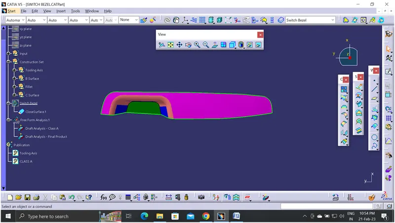
Step 2: Create a point on the base surface using the point command option. Using intersection command along the plane "YZ" and draw the line along the "Z" direction on two side walls. Using bisecting line command Draw a Tooling Axis for reference purpose.
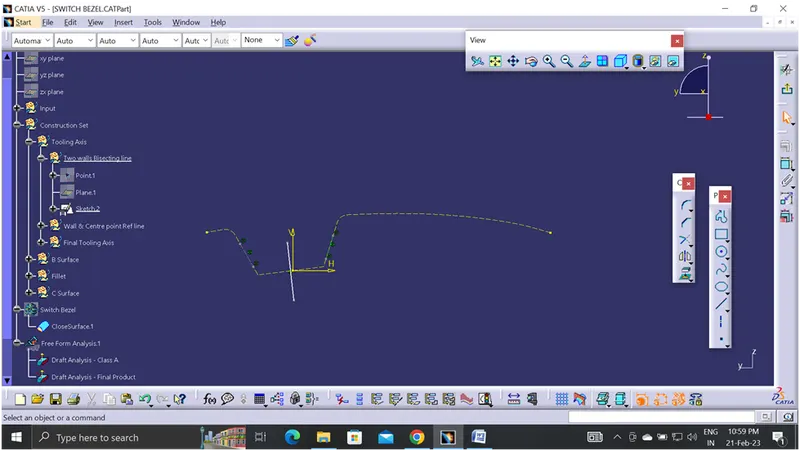
Step 3: Using intersection command along the plane "ZX" and draw the line as a Ref. along the "Z" direction on side walls and other line on the centre of the point, make an angle of 3 deg.
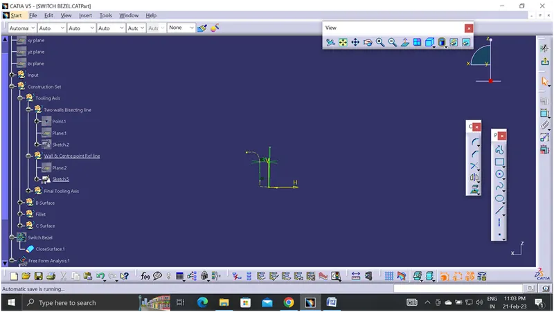
Step 4: Using a Bisecting line command to draw a Tooling axis for the surface
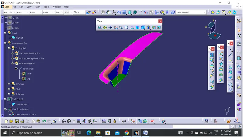
Step 5: For creating the draft analysis, first select the "Customize View Parameters" and select the "Material" option
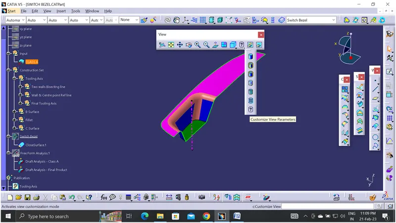
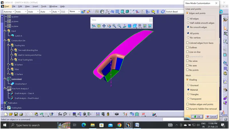
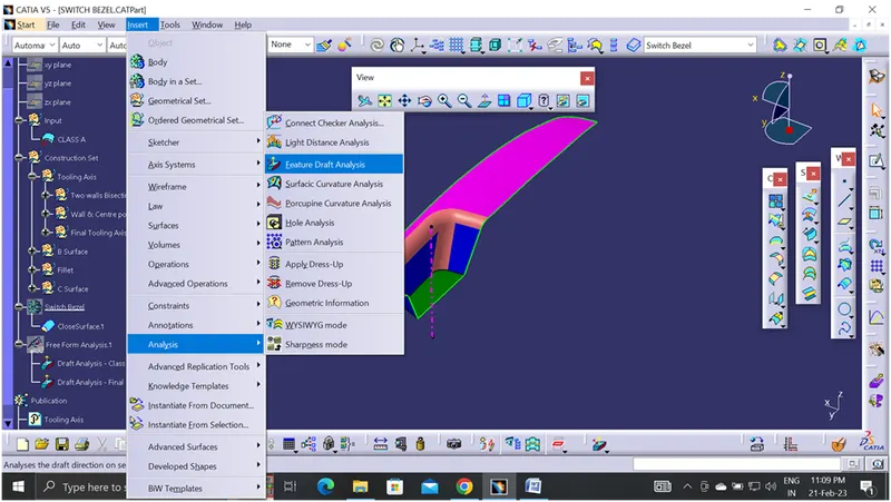
Step 6: Select the Insert > Analysis > Feature Draft Analysis
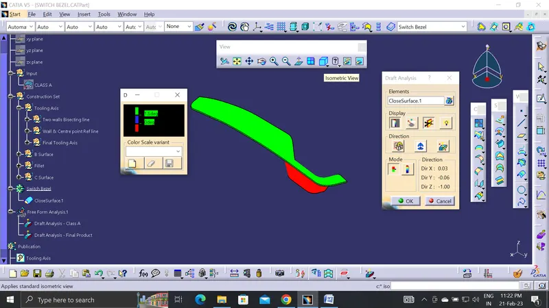
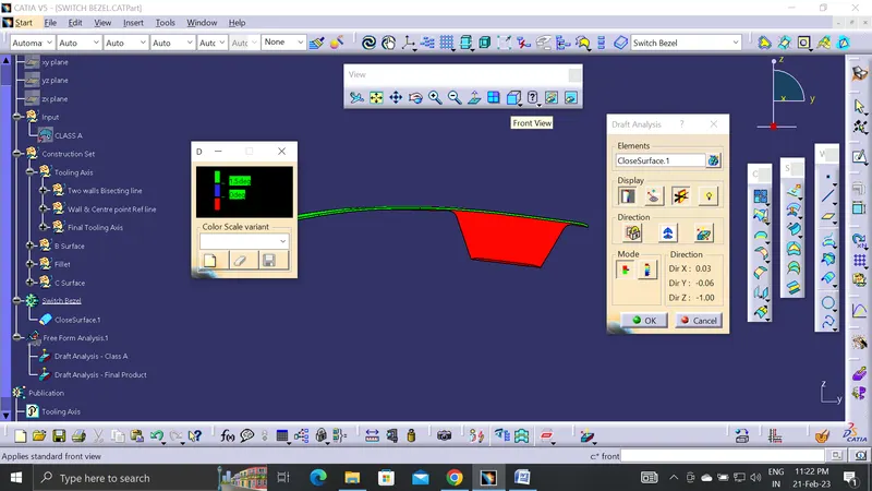
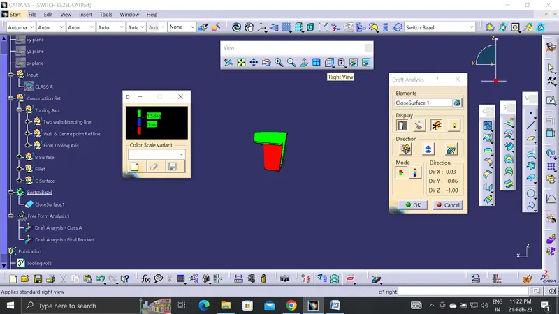
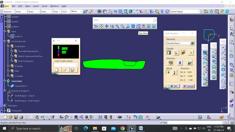
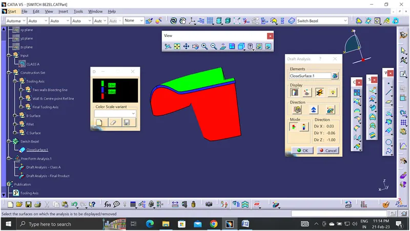
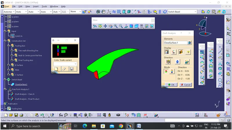
Step 7: Click the "Compass" icon and drag the compass on the Tooling axis and locking it. Make the draft angle as 3 deg. If the Draft angle is more than 3 deg. It shows a Green colour and 0 deg it shows in yellow colour. If the Draft angle is less than 0 deg its shows in Red colour.
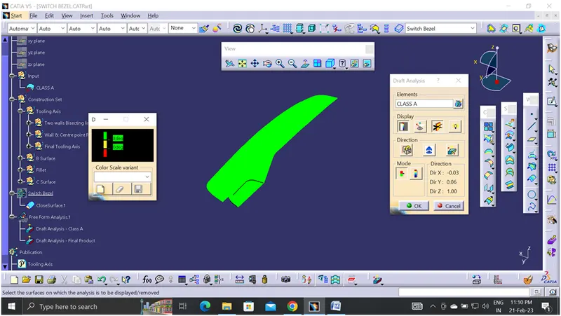
Step 8: Finally our Class A Surface pass the draft analysis test.
Step 9: Same procedure is follow the final part. This means joining of Class A, B Surface & C Surface. Our final output part also clears the Draft analysis.
If we give Draft angle is 3 deg. The sweep area of the class a surface is making blue colour
If we give Draft angle is 1.5 deg. Our final part model clears the draft analysis test completely.
View Mode: