Week 8 - Challenge 2 - Base Bracket Design
AIM
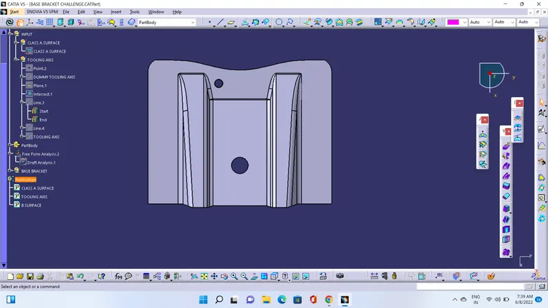
Create the Base Bracket Plastic component through the given Class-A surface. To begin with, the tooling axis for the given Class-A Surface should be created meeting the requirements of the draft angle and at the end perform the Draft analysis on the model.
PROCEDURE
- Creating point
A point is created in centre of hole by using point tool and hole as reference.
- Creating a dummy tooling Axis
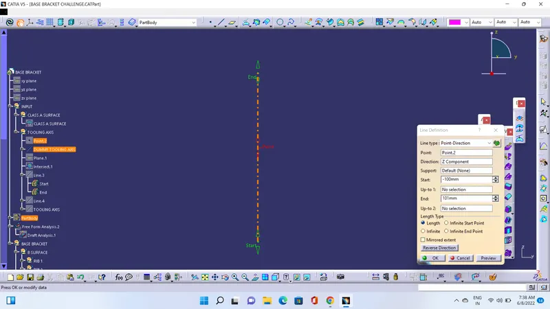
Using line tool a dummy tooling axis is drawn along Z direction.
- A Plane is created at the refereence point
- Intersect
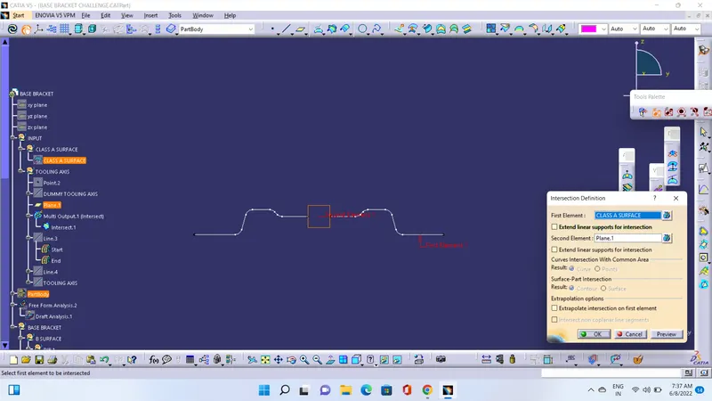
Now using the inetersect option on the toolbar, select class A surface as the first element and plane 1 as the secont element. This will give A 2D skecth of base bracket viewing from X direction.
- Creating line on side walls
Create two lines from the points on the side lines of the sketch using point to point in line command.
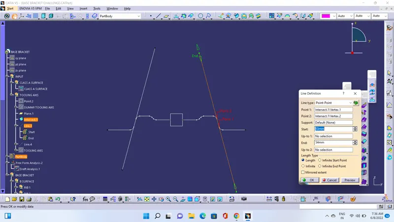
- Creating tooling Axis
Using the 2 lines, create a tooling axis . Create a line that bisects these two lines from the reference point in the Z-direction. This will create a tooling axis.
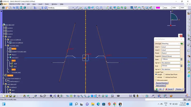
- Draft analysis
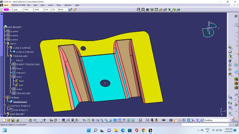
To perform draft analysis on the model:- Go to menu bar > select insert > Analysis > Feature Draft Analysis. To give the draft direction, use the compass and align Z-axis of it with the tooling axis. Once it properly aligned, lock the draft direction. A red point shown in the screen, select Base Bracket and it will show us the current of the model. Then go to display tab on draft analysis and select show Colour scale option and it will show the draft value. Set the Draft value to 3 deg under the colour scale variant and press ok.
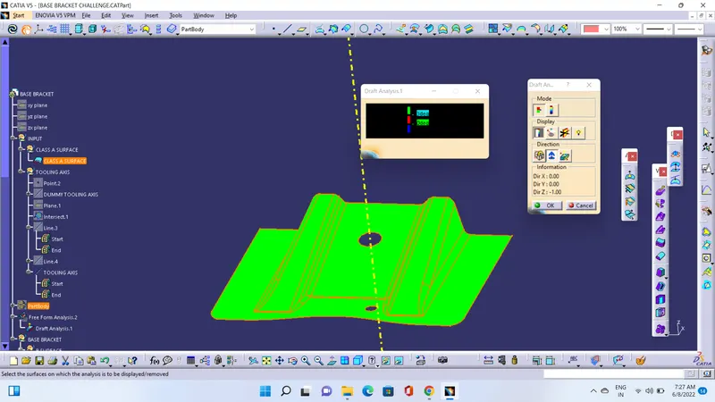
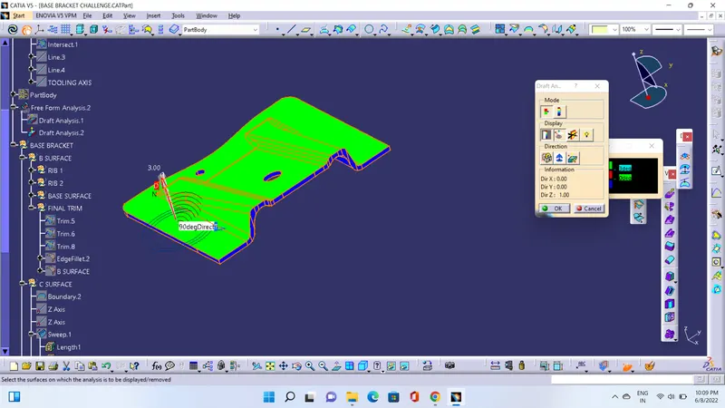
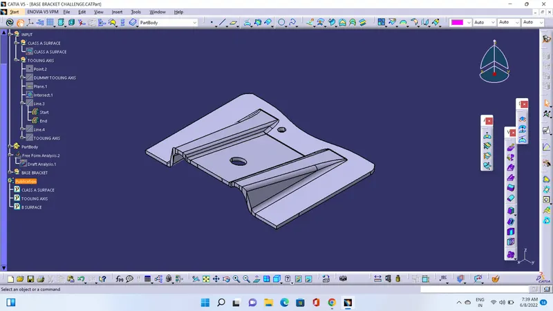
ISOMETRIC VIEW
FRONT VIEW
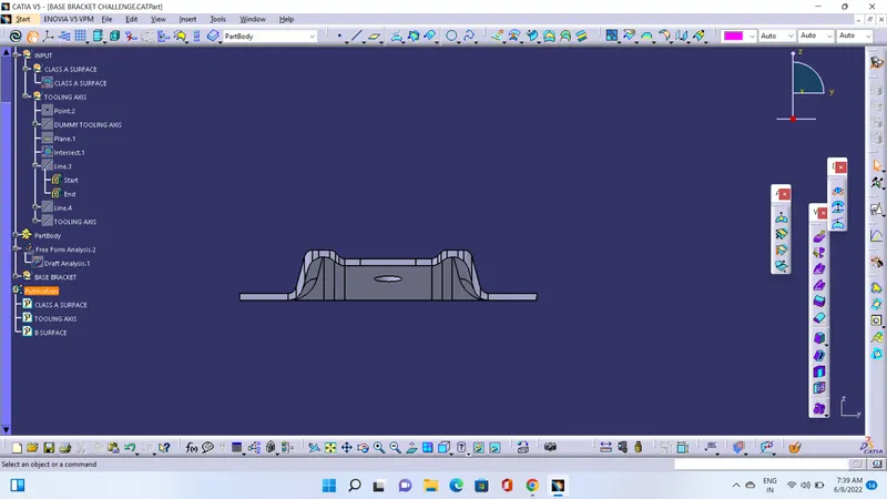
TOP VIEW