Week 8 - Challenge 2 - Base Bracket Design
The Draft Analysis command enables you to detect if the part you drafted will be easily removed. This type of analysis is performed based on color ranges identifying zones on the analyzed element where the deviation from the draft direction at any point, corresponds to specified values.
Class A surface
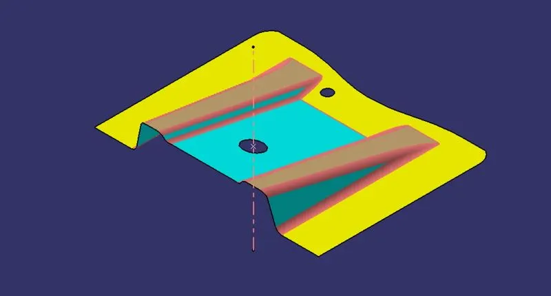
First import the class A surface provided into the catia V5 software
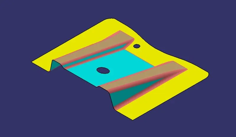
The dummy axis was created for reference
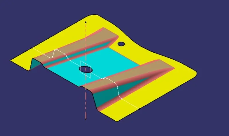
Then using the intersection command the cross section of the surface has been found in X axis direction
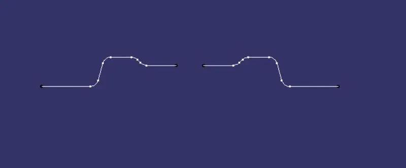
The two lines were drawn to get a exact center line. By using those two lines the tooling axis was crated using intersection line command
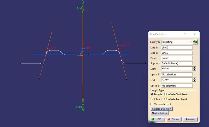
The axis is named as main tooling axis
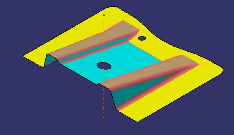
For draft analze the surface changed into material mode

Then the compass was defined as per our requirment
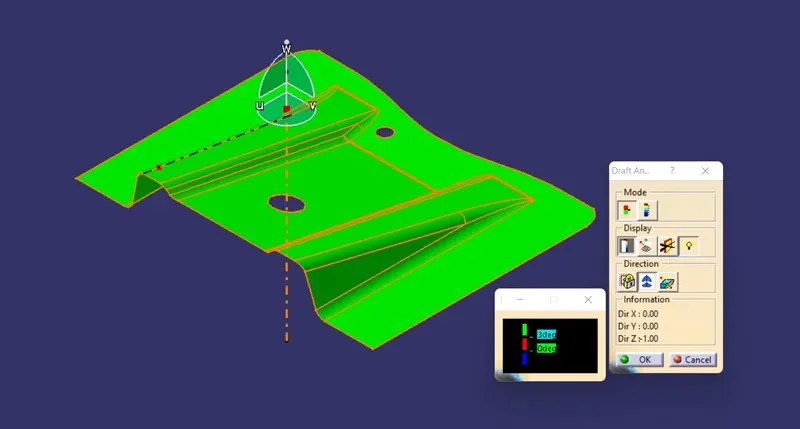
As we can see in the above image the minimum draft for the surface is 3 degree. So the surface is fine for further process.
Views for draft analysis
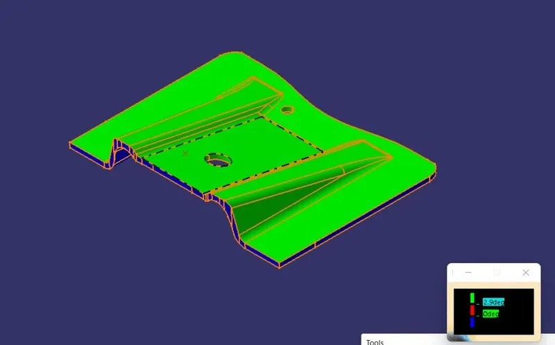
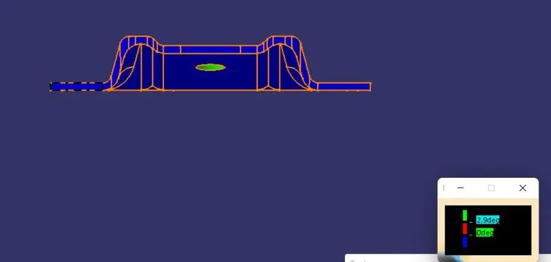
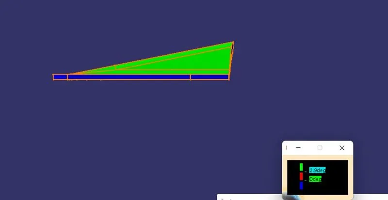
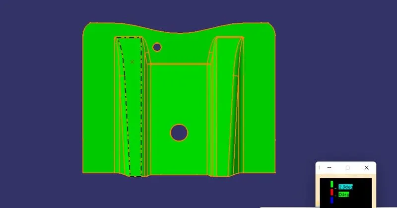
Then for creating B surface the following processes were followed.
The two ribs were taken from the class A surface using extract command.
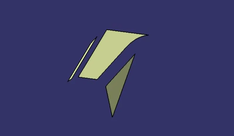
Then the surfaces were untrimmed to get a defined shape.
Used the extrapolated command for extended shape the surfaces.
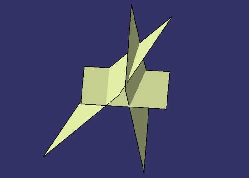
Then the surfaces were trimmed
The same above process were conducted for the another rib also.
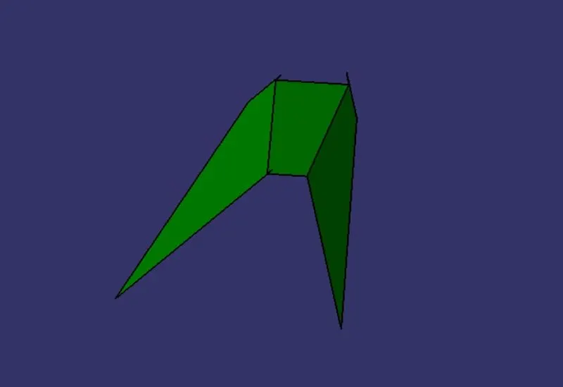
The flat surfaces also extracted from class A surface
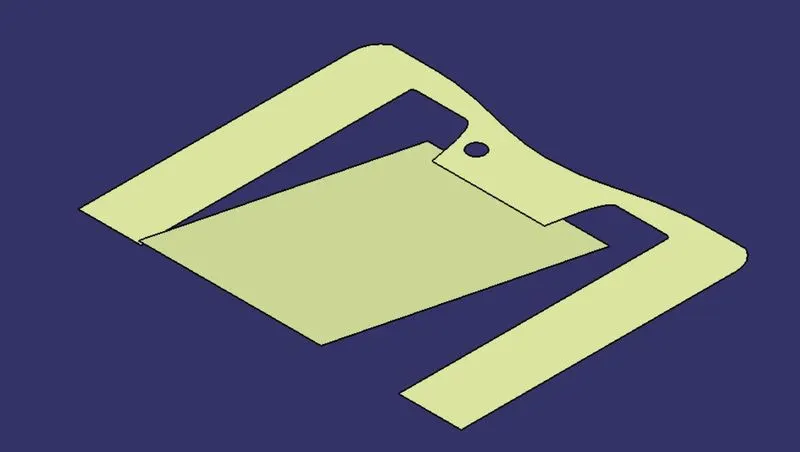
Trim those surfaces to get a desired output.
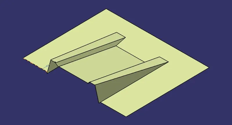
To create the class C surface
The boundry of the class A surface created then it was sweeped along the tooling axis direction.
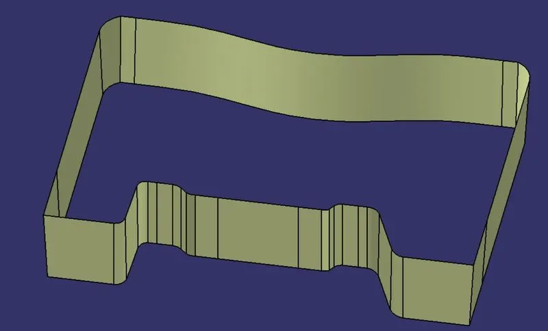
Same for the two holes on the class A surface
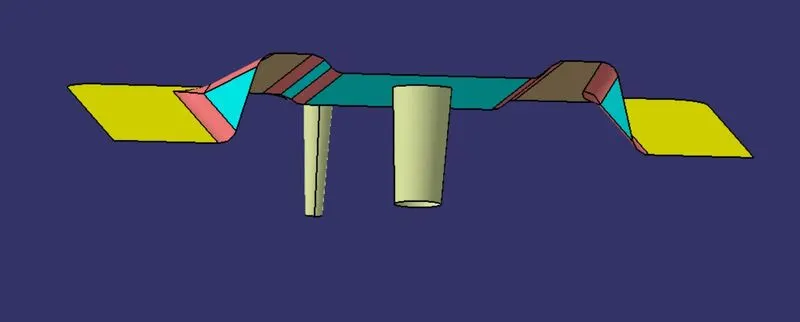
Then join class A surface and class C surface.
Then this joined surface trimmed by using the class B surface.
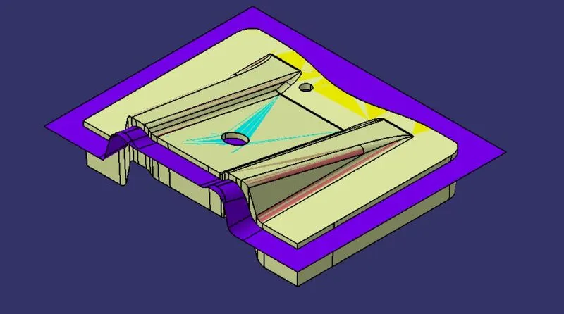
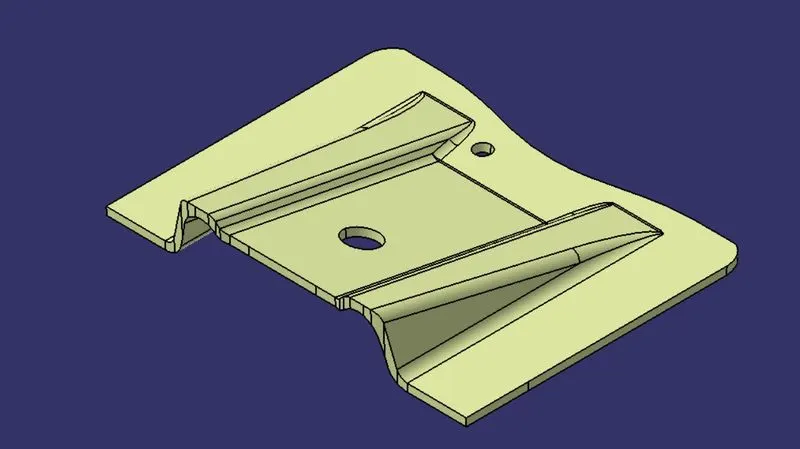
The resulted surface then solidified by using the closed surface command in the part design.
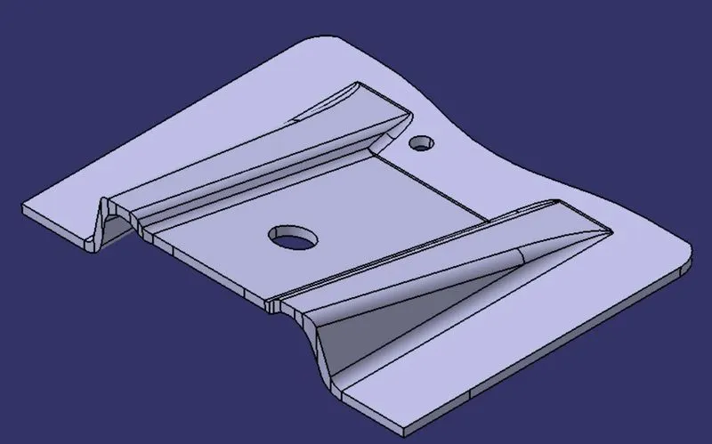
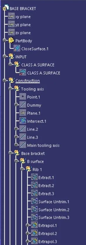
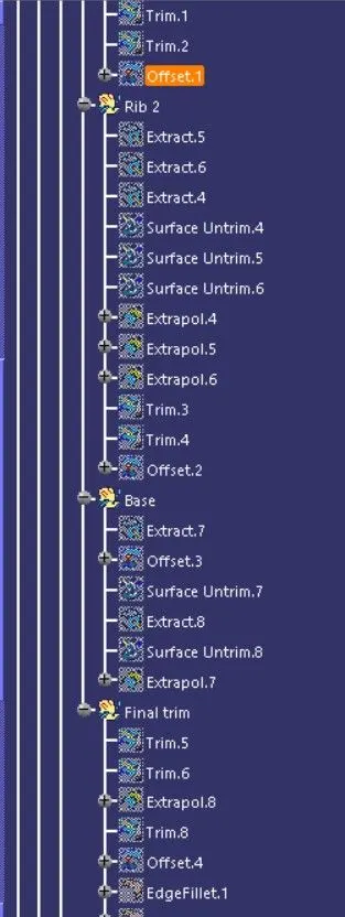
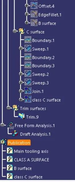
Tree structure