Door Arm Rest Week 8 Challenge
DOOR ARM REST DESIGN AND DRAFT ANALYSIS
AIM:
To create the door arm rest and add thickness, and to perform the draft analysis by creating tooling axis.
PROCEDURE:
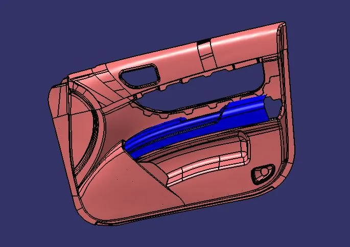
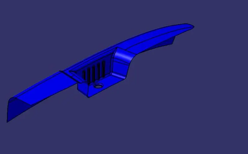
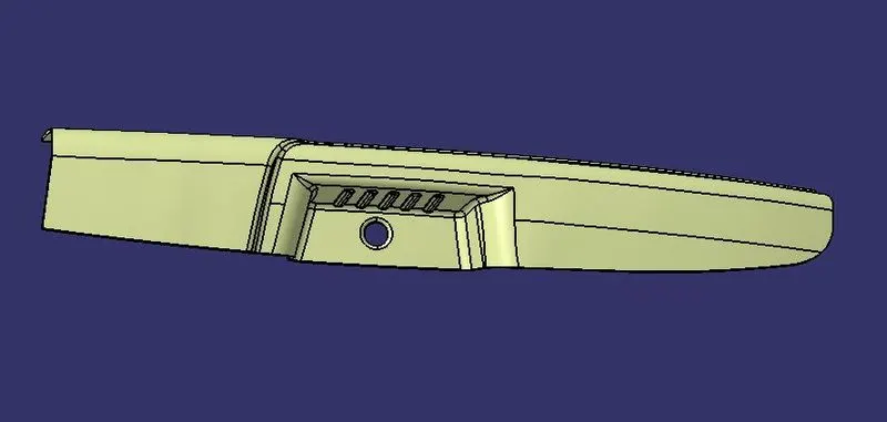
Before starting the design of the component we have to check the class-A surface for any discontinuities using the boundary command, this command will specify the boundaries which are not closed in the green colour, if there are any open edges are seen in the class-A surface we have to close the gap, otherwise we can start working. Here the door arm rest and the reference for door is also given.
TOOLING AXIS CREATION
As the first step we have to check the class-A surface if the proper draft is given or not, so we have to create an axis system to create the tooling axis. For creating an axis system we need a point on the surface, so we have to extract the bottom surface, un-trim it and put the point in the geometrical centre by simply entering 0 in the dimension of the point, this steps are shown below
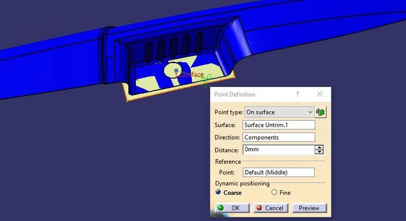
After creating the point we need to place an axis system on that point, we have make sure that we don’t select current option in the axis system.
BISECTING METHOD OF TOOLING AXIS CREATION
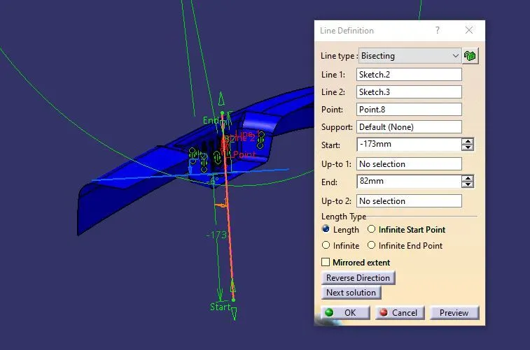
In this method the tooling axis is created by bisecting the two lines, this bisecting line needs two lines and a point to create a bisecting line.
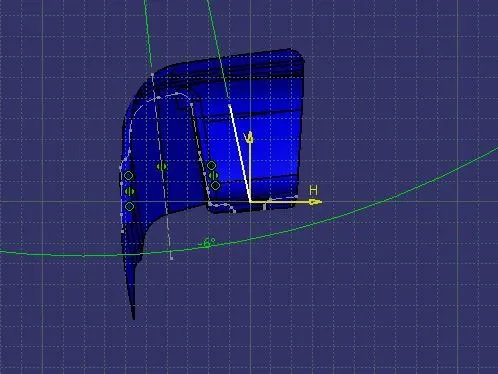
Then we have to select plane which intersects the class-A skin and we have to us the intersect 3d elements option to intersect the class-A skin on the plane and make them construction draw two line on the each side of the lines as shown in the picture and now use the bisecting line command and select the two lines to execute the command similarly create the sketch and bisecting line for the other side also in that side we have one face only other face is not present there so we have make a line of our own with a random angle value of -6 degree we can also change the degree if the draft is not achieved, the following images shows the procedure for tooling axis creation.
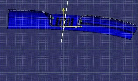
with respect to the above two lines an another bisecting line is created and this bisecting line will be the main tooling axis it is shown below, how to create it with bisecting method.
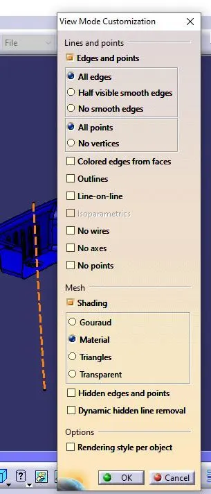
Now we have created the tooling axis, so we can perform the draft analysis. To perform draft analysis we have to put the customize view parameters mode in the view mode and after entering into customize view mode we have to select the material mode as shown in the below image
Then perform the draft analysis by selecting the draft analysis icon or by selecting Insert-Analyse-Draft analysis, then we have to select the compass icon on the direction tab of the draft analysis tool bar.
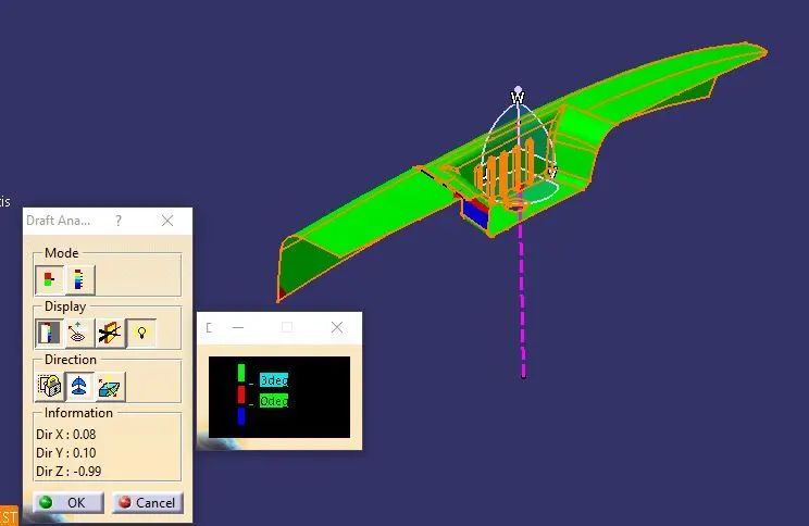
And place the compass on the tooling axis by picking and dragging it on the middle point of the compass, after that press the lock icon on the same tool bar, and click on the any of the surface of the part to perform the draft analysis.
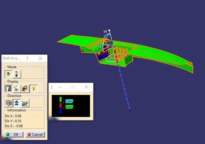
In that small colour code dialog box shows the value of the degree and the maximum and minimum values, this values also can be changed by selecting on the colour codes of the small dialog box, here the draft degrees on that part less than 3 degree will be shown as red colour, and below zero is shown as blue colour, and the values above the 3 degree is shown in green colour and it shows that the part can be manufactured and adequate draft is given.
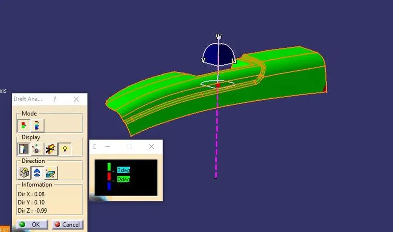
Here we can see that some of the areas are shown the red colour, which shows that those areas cannot be cleared in main tooling itself, so it needs another side core tooling axis in order to clear the areas which cannot be cleared by the main tooling direction.
We have to follow the same steps which we used to create the main tooling axis for the side core tooling axis creation it is shown in the below steps we have to select plane which intersects the class-A skin and we have to us the intersect 3d elements option to intersect the class-A skin on the plane and make them construction draw two line on the each side of the lines as shown in the picture and now use the bisecting line command and select the two lines to execute the command
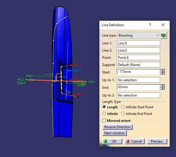
Now we have created the side core tooling axis, so we can perform the draft analysis. To perform draft analysis we have to put the customize view parameters mode in the view mode and after entering into customize view mode we have to select the material mode,Then perform the draft analysis by selecting the draft analysis icon or by selecting Insert-Analyse-Draft analysis, then we have to select the compass icon on the direction tab of the draft analysis tool bar.
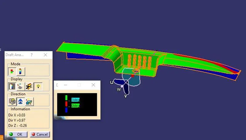
And place the compass on the tooling axis by picking and dragging it on the middle point of the compass, after that press the lock icon on the same tool bar, and click on the any of the surface of the part to perform the draft analysis.
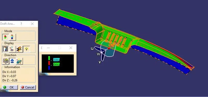
In this draft analysis most of the surface is shown in green colour which is shown in red and blue colour in the main tooling direction, so the area which is not cleared in the main tooling direction is also cleared in this side core tooling axis.
After checking the draft, we have to design the b-surface and c-surface we have to extract the top surface and offset it according to the thickness of the part, un-trim it, extrapolate it. Here we have to extract the surfaces separately for the top and side surfaces of the class-A surface.
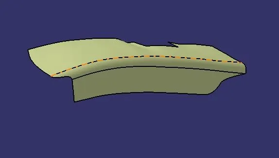
Also extract the wall surfaces of the class-A surface and un-trim and extrapolate it, also do the same steps for base surface also.
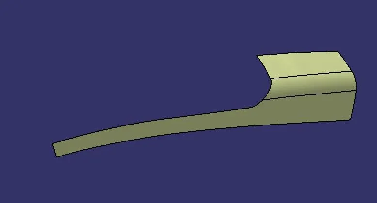
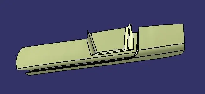
Now we have to trim the surfaces of the both wall surface to make the side surface of the component, after that we have to publish the b surface. Apply the correct size of fillet to maintain the wall thickness uniformly.The complete B-surface is shown in the below image,
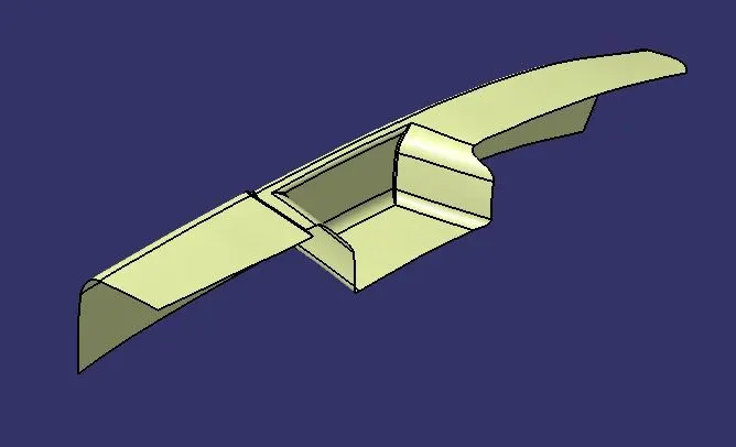
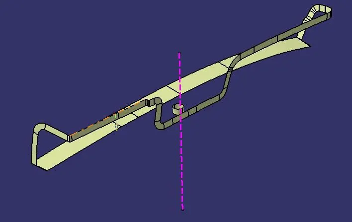
After creating the B-surface we have to create the C-surface, we can create the C-surface by executing sweep command by extracting the boundary of the class-A surface, here we have to extract the boundary in several parts and make sure that we use smooth curve option to make the sweep as smooth as possible and also in a the tooling direction.
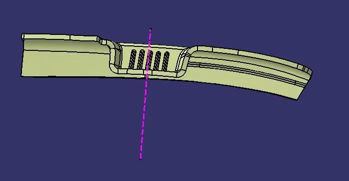
after creating the C-surface we need to trim the class-A surface with the C-surface created, now we have to trim the B-surface with the trimmed A-surface,this creates a full surface model as shown in the below image,
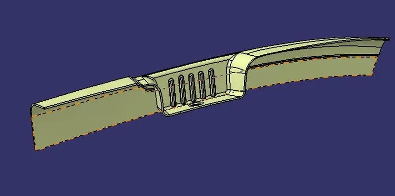
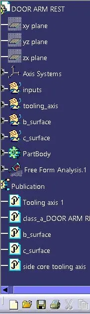
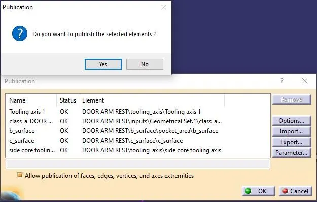
Once after creating the tooling axis, and B-surface and C-surface we need to publish them by using the tools dropdown publish icon, and we have to select the features we are going to publish in the feature tree and give ok to the dialog box appears on the screen.
After creating the complete closed surface model, we have to use the close surface command in the part work bench to create the complete solid model out of the surface model. After creation of the solid model we have to perform the final draft analysis for the complete solid where we have to do the same steps aswe did in the draft analysis for the class-A surface. It is shown in below image
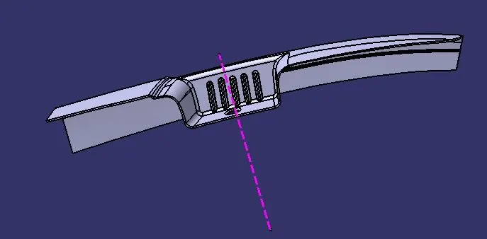
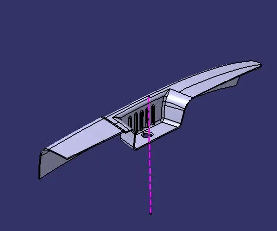
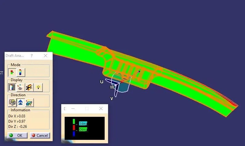
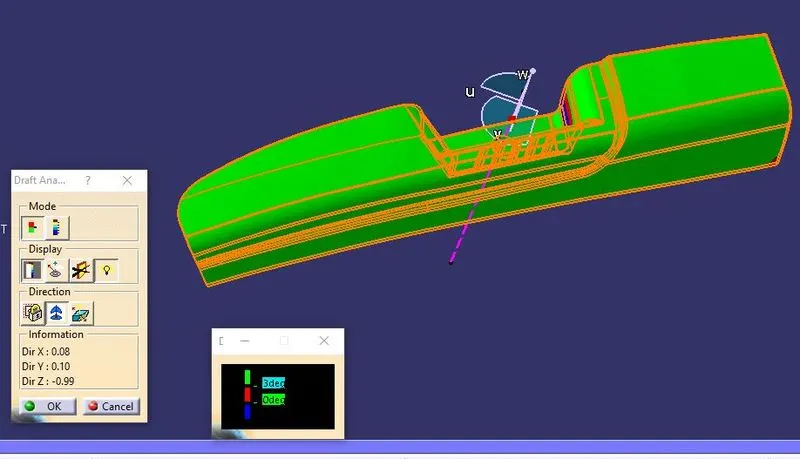
Here also the draft analysis for the main tooling and the side core tooling axis is shown. And the side core tooling axis clears the area which cannot be cleared in the main tooling axis.
CONCLUSION:
Thus the design and draft analysis is done for the door arm rest.