Week 8 - Challenge 2 - Base Bracket Design
Design of a Base bracket and draft analysis
Objective:
- Design a base bracket from the given class A surface
- Performing draft analysis of the class A surface
- Making Class B and Class C surface
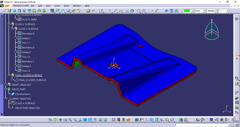
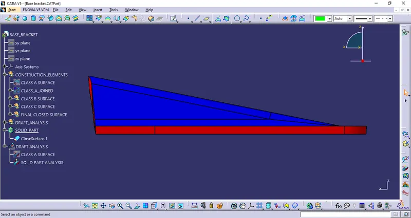
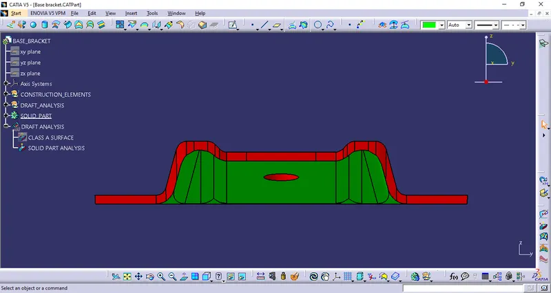
- Performing draft analysis on the final solid part
Draft Analysis of the Class A surface:
1. Make a Dummy/Temporary tooling axis, using line command:
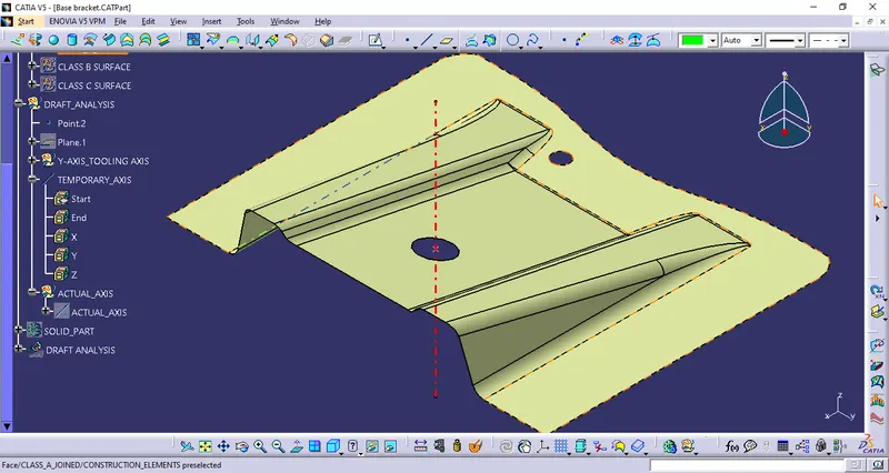
Y-Direction tooling axis:
1. Make a plane in the center, on the Y- Plane:
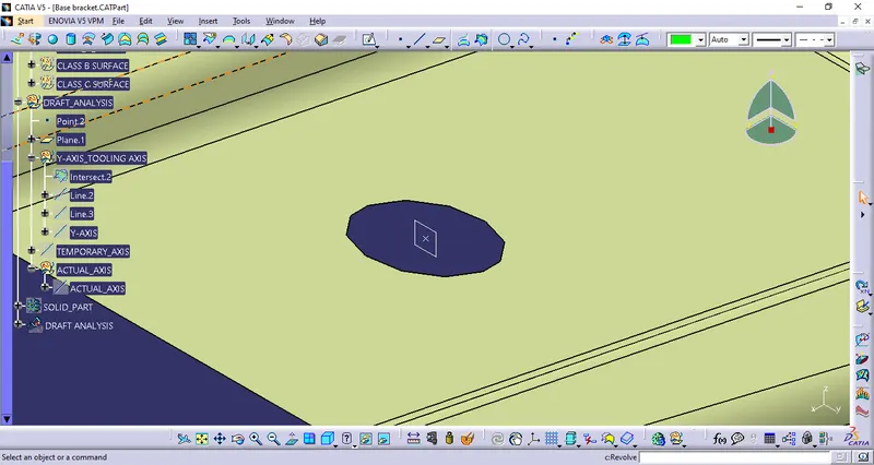
2. Using intersect command a profile is created for the Y-Direction:
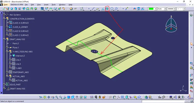
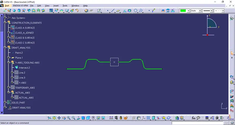
3. Two lines are created at the inclined edges of the profile:
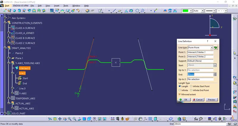
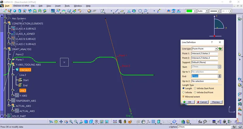
4. Using line option, bisecting option, choosing the two lines and the midpoint the Y-Axis tooling axis is made
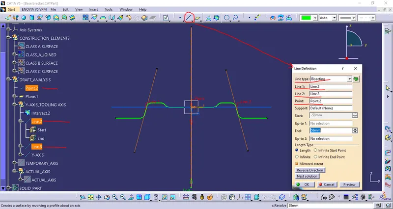
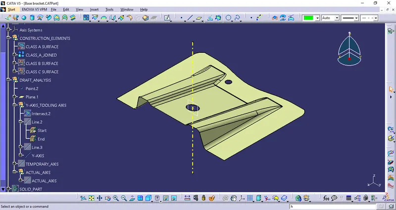
Tooling axis in X-Direction is not needed ad there is no incliend profile on both side
Final tooling axis:
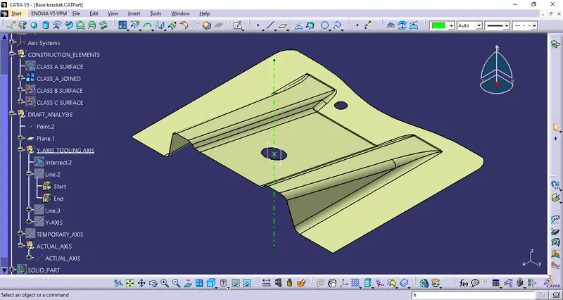
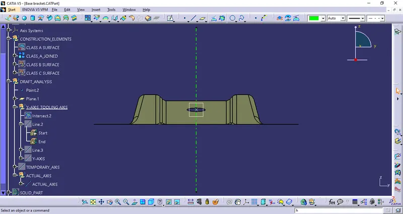
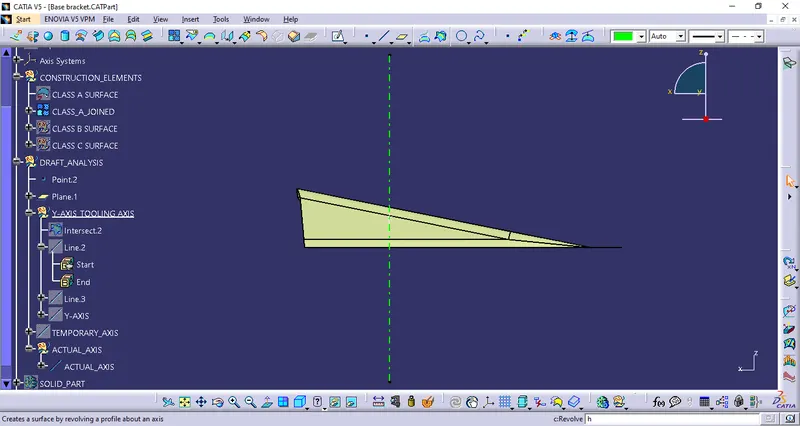
Draft analysis:
1. By using draft analysis command, draft analysis is performed on the given class A surface
2. By using compass option the compass is placed on the tooling axis:
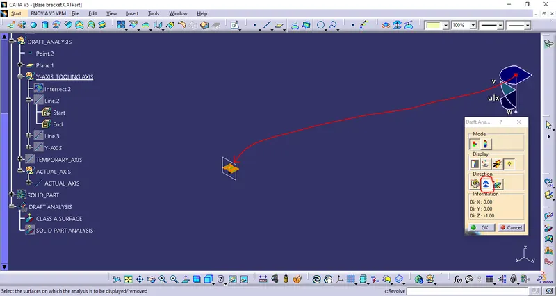
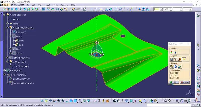
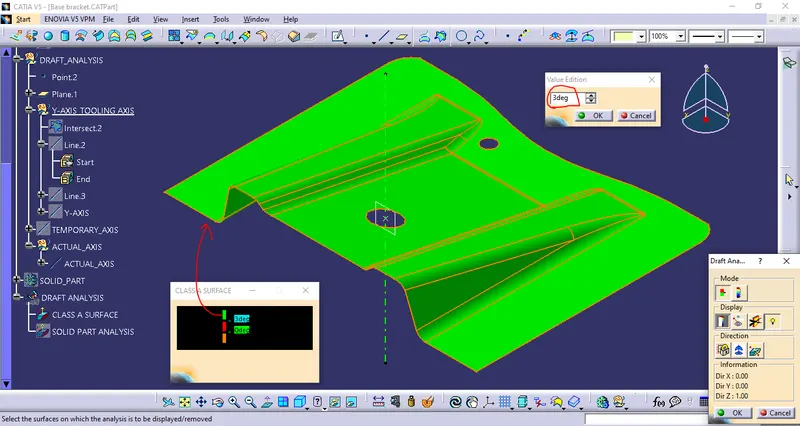
After performing the draft analysis, it was found that the class A surface has a positive draft, Minimum draft of 3 degree is kept:
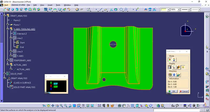
Bottom View:
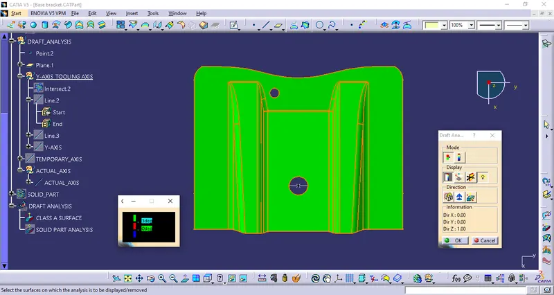
Top View:
Class B surface:
The class B is surface is 2.5mm below the class A, so the part has a thickness of 2.5mm
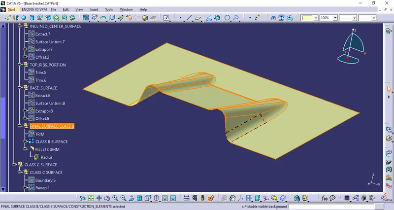
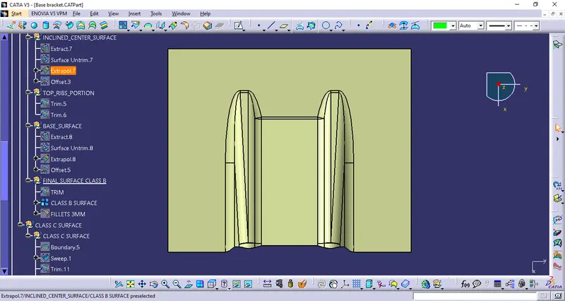
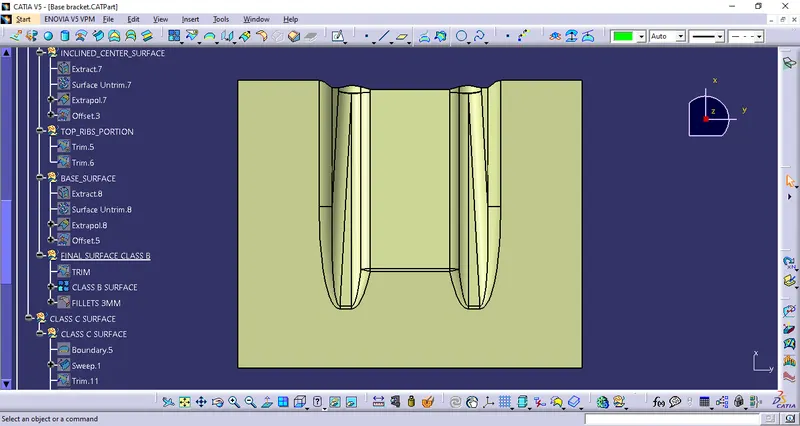
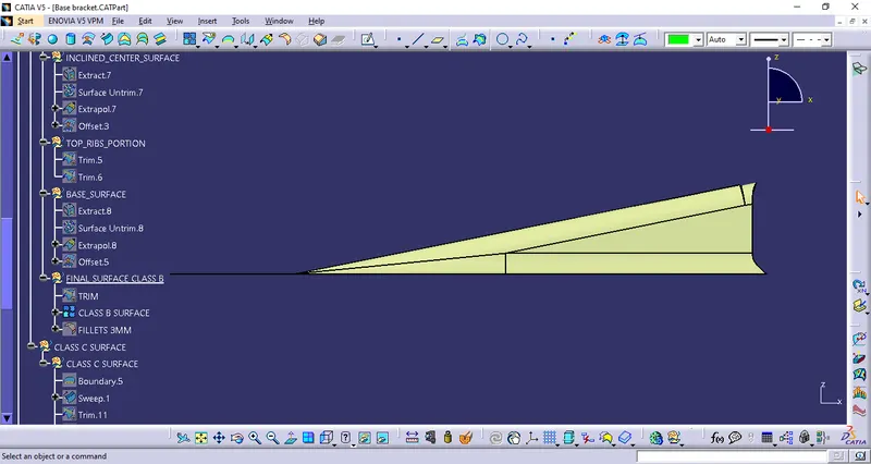
Class C surface:
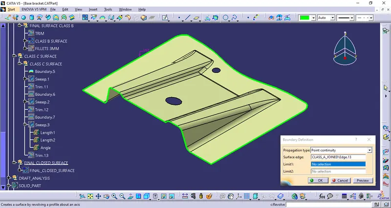
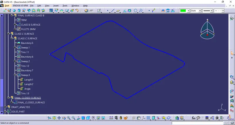
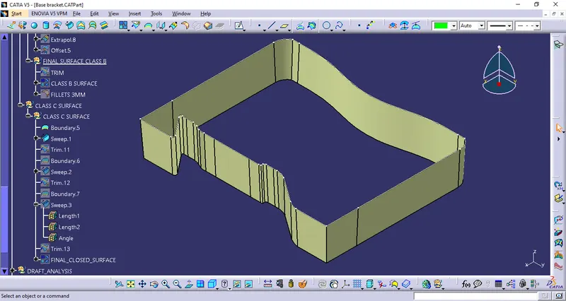
The Class C surface is made by creating the boundry of the Class A surface and then using sweep option:
All surfaces:
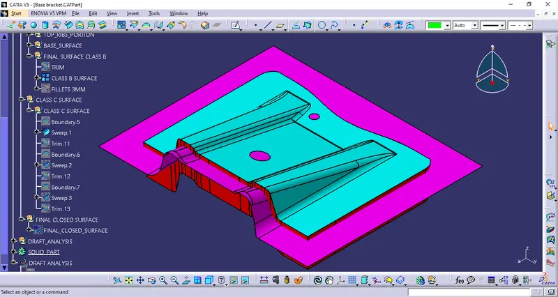
Blue: Class-A
Pink: Class-B
Red: Class-C
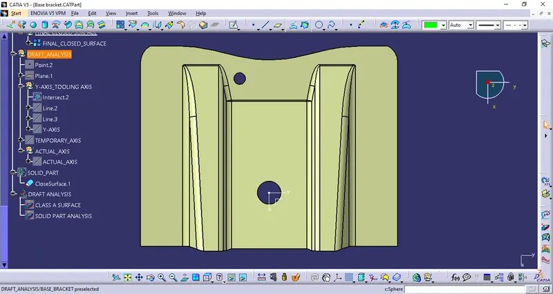
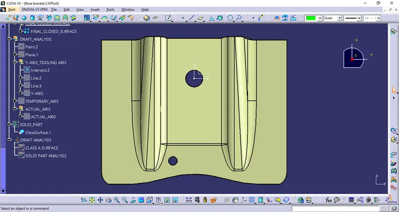
Final Closed surface:
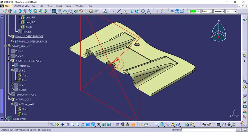
Closed surface and final part with expanded feature tree:
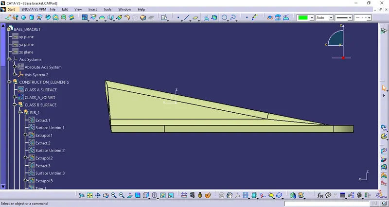
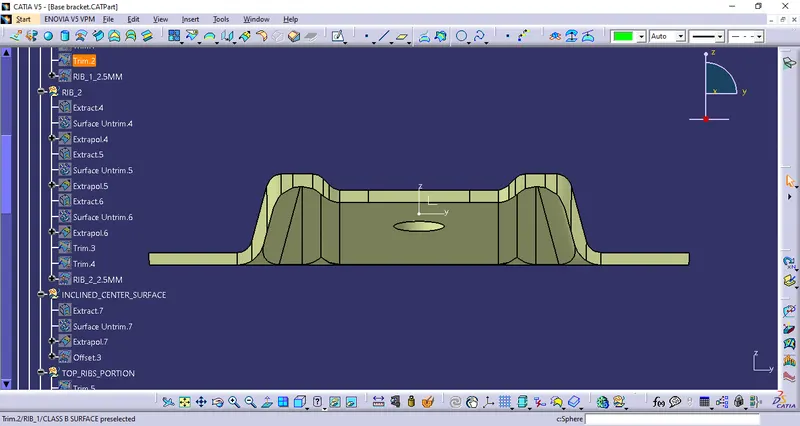
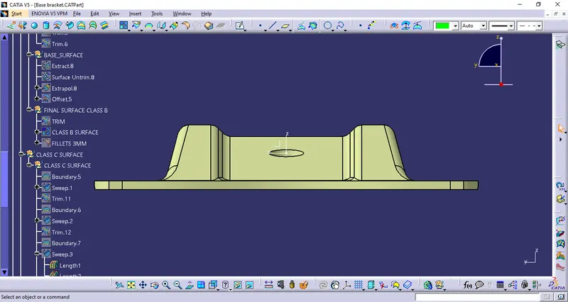
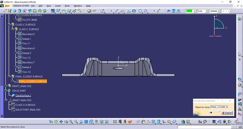
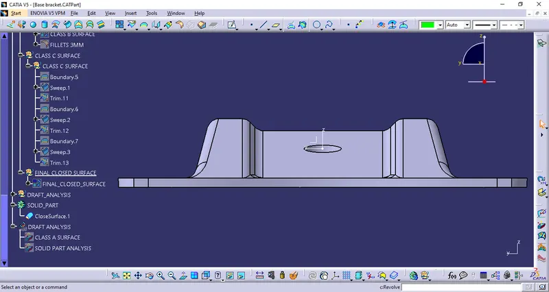
Solid part:
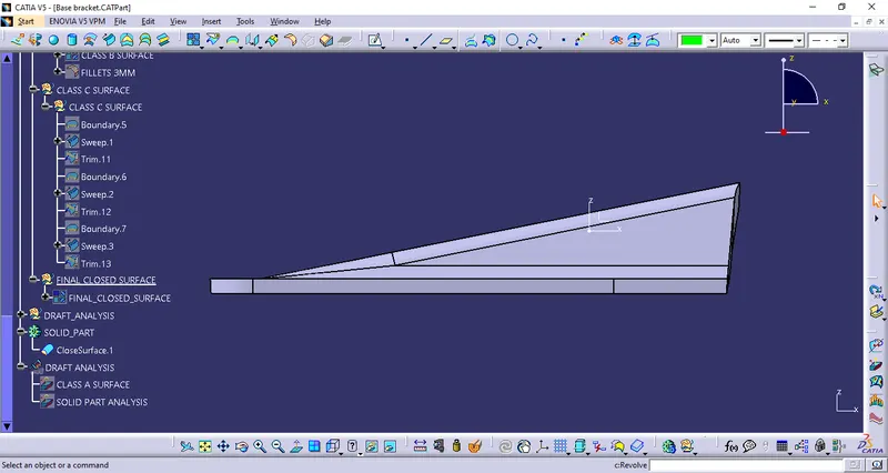
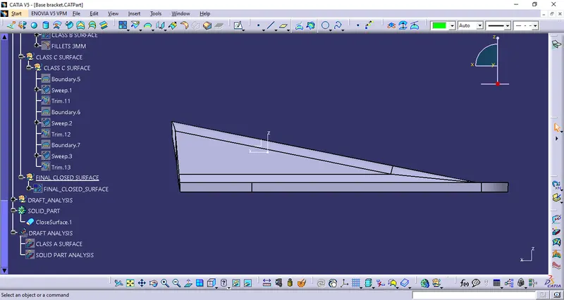
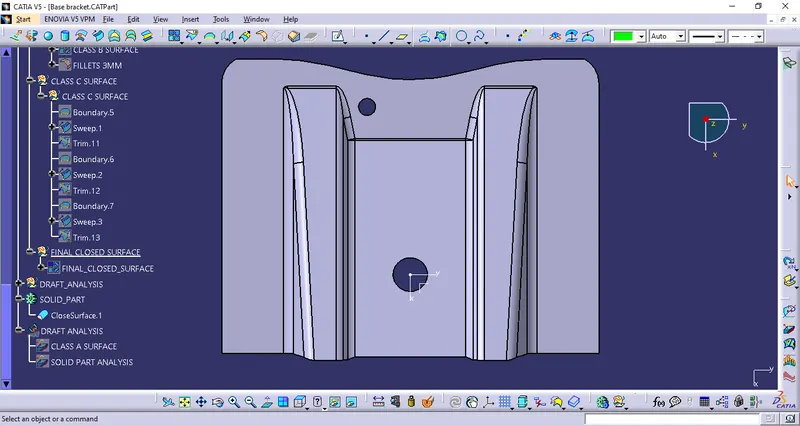
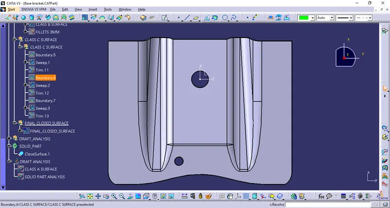
Closed solid command (Part Design) is used for making the solid surface:
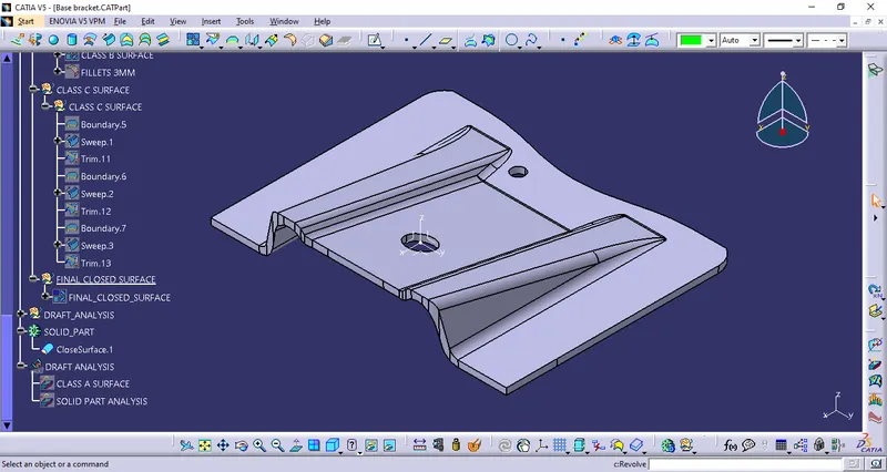
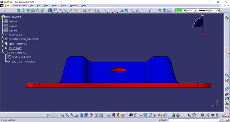
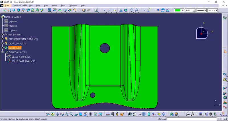
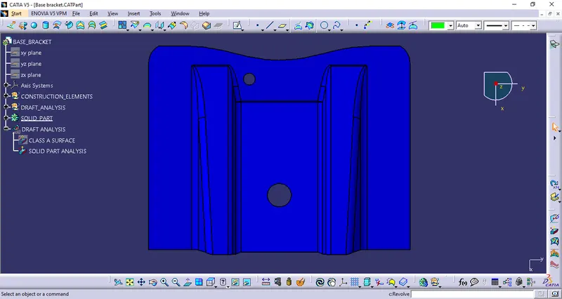
Draft analysis of solid part:
Conclusion:
Draft analysis was perfromed on the Class A surface and the part was found to have positive draft. The Class B and Class C surface was created using the class A surface. Closed solid command was used for making the solid plastic part. Draft analysis was done on the solid part as well.