Week 8 - Challenge 2 - Base Bracket Design
BASE BRACKET DESIGN
AIM: -To Create the base bracket plastic component through the given class A surface. To perform the final model draft analysis.
Draft Analysis: - Draft analysis is based on the color range identifying zones on the analyzes element where the deviation of the draft direction at any point of the corresponding specified values. Draft is required on all parts of mold movement in order to allow parts to release or eject from the property.
Draft is the angle in which the part is tapered to allow it to release. At the part cools it tends to want to shrink to the core side of the mold. The draft is allowing the part to release or eject without creating any friction between the surface of component and core and cavity plates.
Minimum draft angle is required 3degree (draft angle is 0.5 is given ideally to the features inside the plastic part) Draft angle vary 5-1 degree but 3-degree draft angle widely accepted. But for automotive sheet metal part the draft angle 7degree or more.
CLASS A SURFACE
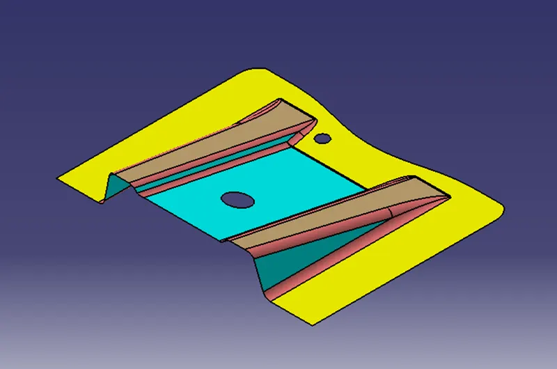
STEP 1: - check the connectivity of given class A surface with the help of join or boundary tool. It has 3 boundaries one has outer and two has inner circle.
STEP 2: -Find out the tooling axis. Tooling axis nothing but the mould opens ort cavity opens.
Check all 3 axis which is best suitable tooling axis .X Axis is possible but its very expensive to manufacture and Y is not possible. Z axis is best suitable for tooling axis.
CREATING TOOLING AXIS ALONG Z DIRECTION
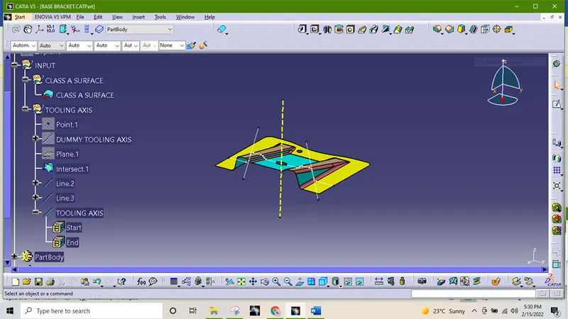
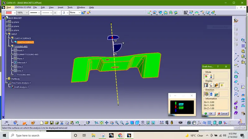
DRAFT ANALYSIS SURFACE A
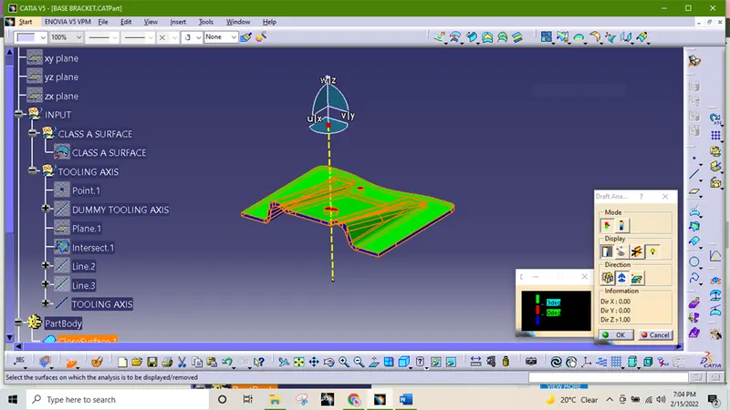
Now perform the draft analysis using featured analysis tool. After opening the draft analysis tool go to compass option and set the compass aligned tooling axis. Click on the lock symbol after aligning and next click on the surface.
CLASS B SURFACE: -
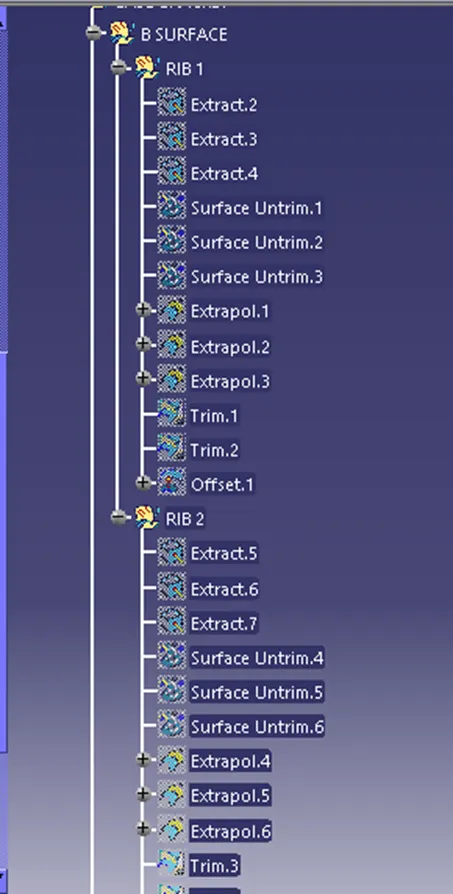
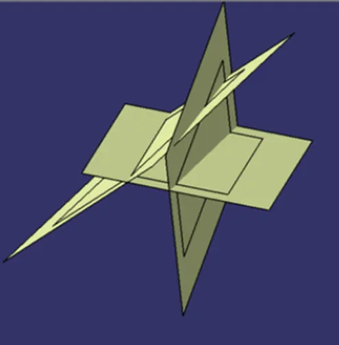
Initially extracting the right-side rib using extract option from class a surface.

After that perform unitrim option and extrapolate in order to increase the length.
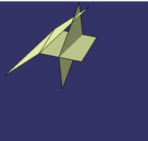
Now trim the surface to required shape
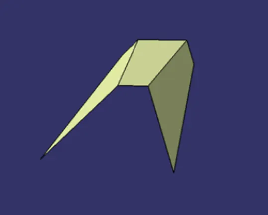
Then offset the surface to get required thickness
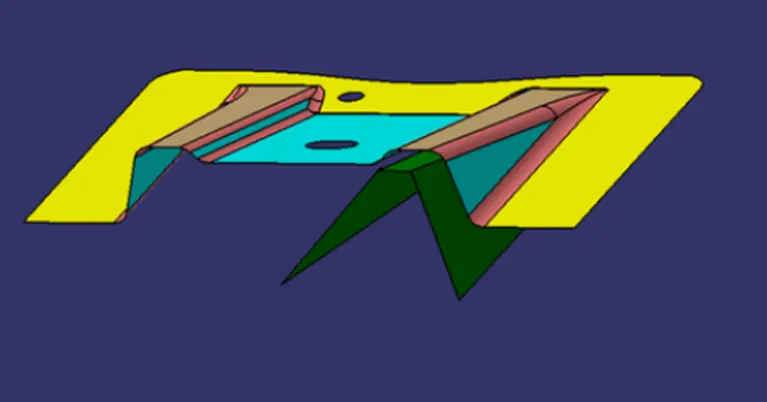
Similarly create the left side rib
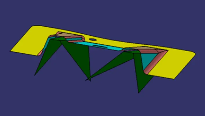
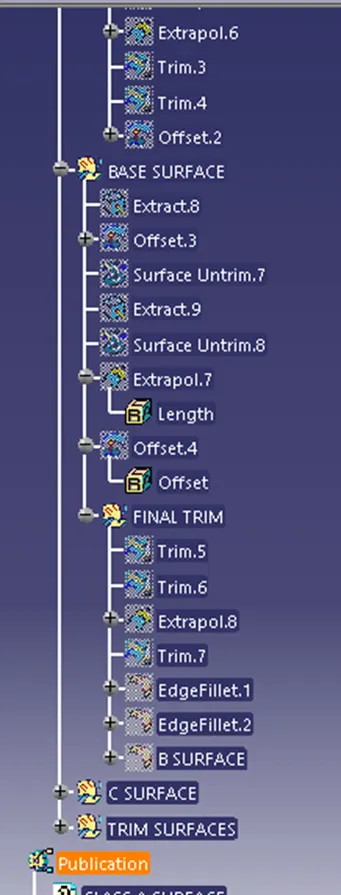
Now similarly get the slanted as well as flat surface and offset it to desired value and trim in order to get required surface. Now applying fillet, the surface required value.
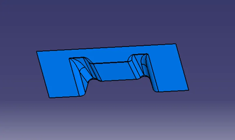
CLASS C SURFACE: -
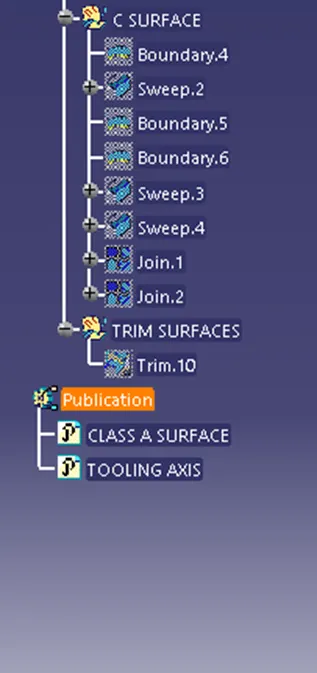
Now creating class C surface take outer boundary of class A surface. Use sweep command to create surface using tooling axis and draft angles as 3 degrees. Similarly takes holes boundary as step 2.
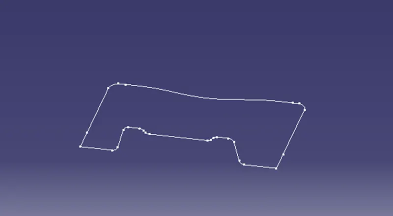
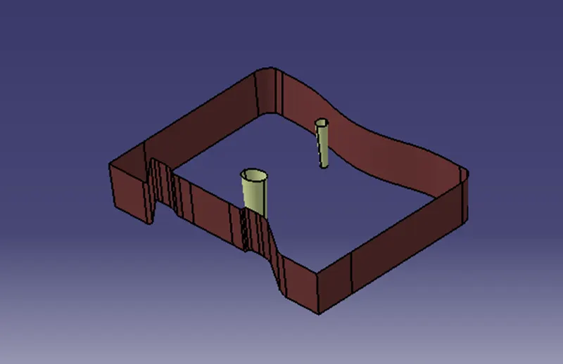
FINAL BODY CREATION: -
First join class A surface and class C surface. Trim resulting surface with B surface. And join the surface.
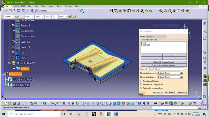
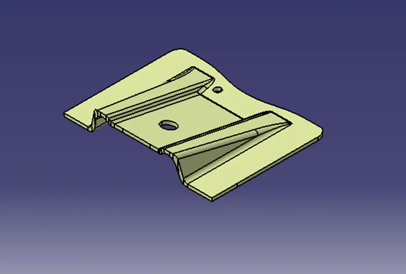
SOLID BODY: -
Change to part workbench < close surface
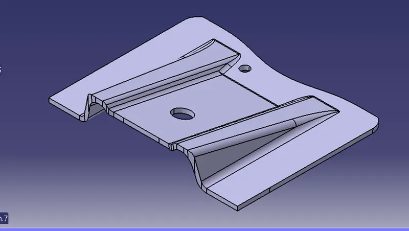
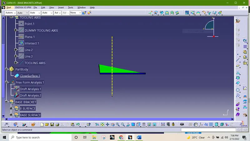
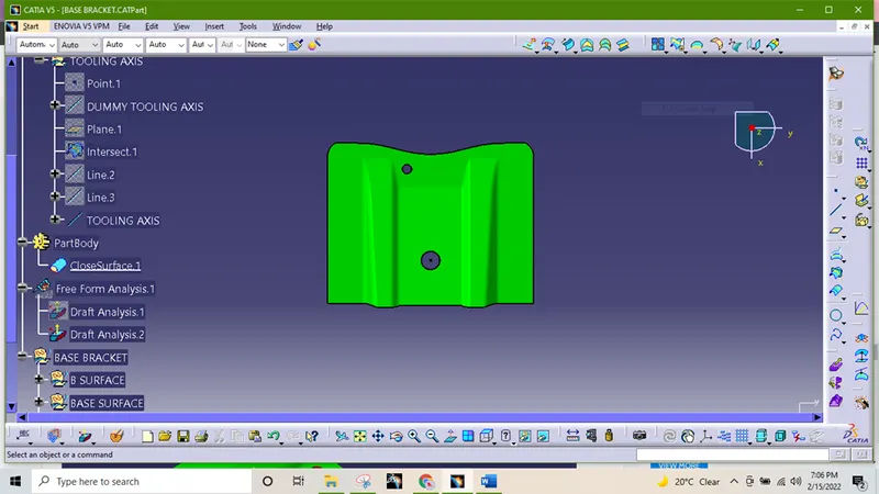
DRAFT ANALYSIS OF FINAL COMPONENT: -
In this process we take main tooling Axis as draft reference.
Final draft analysis
ISOMETRIC VIEW
FRONT VIEW
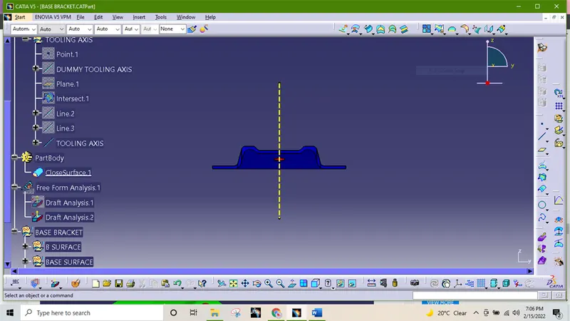
RIGHT SIDE VIEW
TOP VIEW
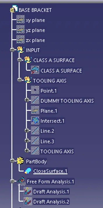
TREE