Week 8 - Challenge 2 - Base Bracket Design
DRAFT ANALYSIS AND PLASTIC COMPONENT MODELLING FOR BASE BRACKET
AIM : To perform the Draft analysis,Tooling axis creation for both the given Class-A surface and the final plastic component
OBJECTIVES :
BASE BRACKET
- Explaining the Draft analysis and the Tooling axis creation.
- Creating the tooling axis particularly the Bisecting method.
- Draft analysis report for both the given Class-A surface and the final plastic component
ABSTRACT :
DRAFT ANALYSIS : The major consideration of Draft Analysis is whether sufficient Draft Angle is provided on the component.Components while designing should be provided with a considerable amount of draft angle depending on the manufacturing consideration.For Plastic components we provide a draft angle of 3 degree.But for Automotive Sheet Metal Parts,it will be from 7 degree or more.
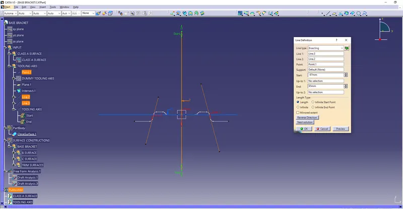
TOOLING AXIS CREATION : The direction in which the mold or core and cavity opens is the tooling axis.With the help of the tooling axis created along the x-axis and the y-axis, these tooling axes are used for creating by bisecting method. Where the two lines and point will be selected as inputs.
PROCEDURE TO PERFORM A DRAFT ANALYSIS AND TOOLING AXIS CREATION IN CATIA
STEP 1
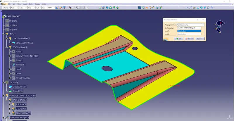
Connectivity of Class-A surface : First checking the connectivity of the CLASS-A surface,this can be done by creating boundaries or by using the join command and see how well it is connected.Just ensure there is no surface gap between component or surfaces.This is the first design step to check continuity and the Quality of the CLASS-A surface.
STEP 2
Analyse visually for the best possible tooling axis for the component.
Checking possibilities in all three x,y and z axis directions and finding what are the problem creation parts of the component.
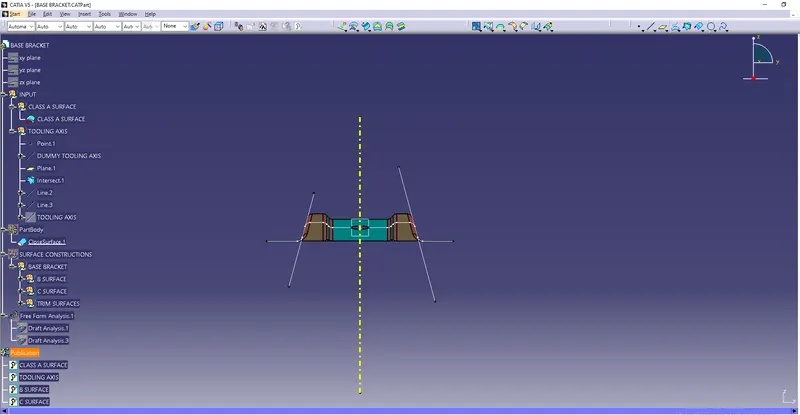
The clearance checking along all the axis direction will be done by creating an intersection along an axis on a plane by creating a new axis system with the model and constructing two lines contact with the walls, the line bisecting the two lines and passing through the point will be tooling axis.
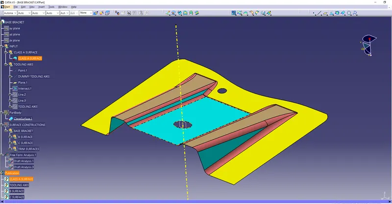
A Dummy tooling axis will be directly created using point-direction command after creating boundary for CLASS-A surface and creating intersection with the model
TOOLING AXIS CREATION :
Using the intersection created lines will be created along the inclined walls,these lines are used for creation of tooling axis by bisecting method where are two lines and point will be selected as inputs.
Creating intersection for checking along X-axis
Using the tooling axis created along x-axis, these are used for creation of tooling axis by bisecting method where the two lines and point will be selected as inputs.
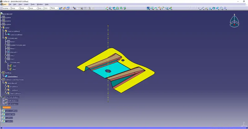
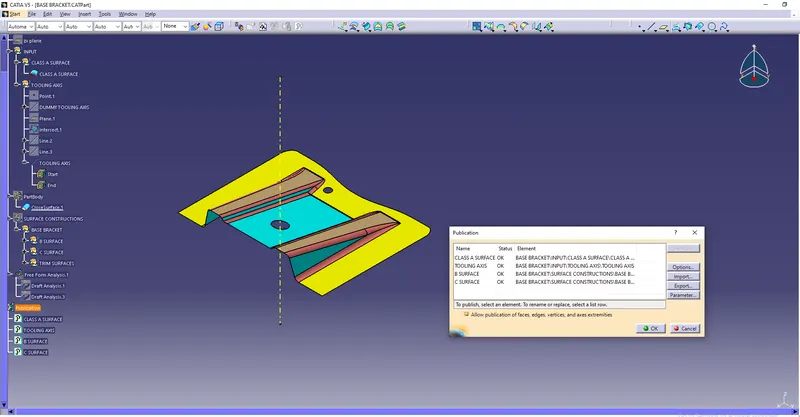
Publication :
Publication is used to make easily accessible of the published components
Draft Analysis :
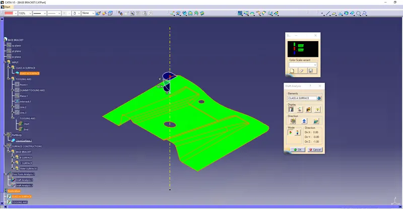
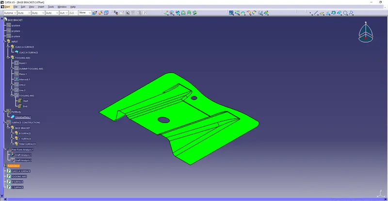
Draft analysis is done after determining the tooling axis,draft analysis is used to check whether the minimum draft 3 degree is maintained or not.
Compass is used to define the draft direction
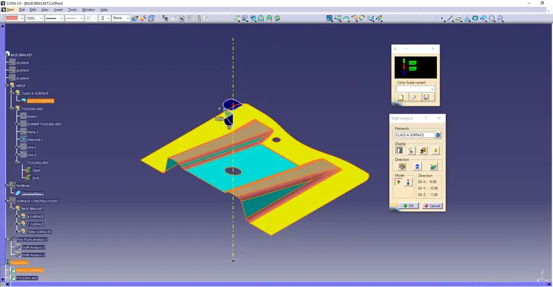
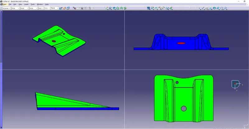
If the minimum draft 3 degree is provided the whole component changes into green colour.
CLASS-B surface:
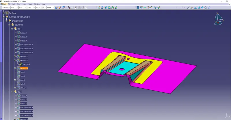
CLASS-B surface is created by extracting each walls and un-trimmimng and extraploating the walls to obtain the shape by trimming the excess surfaces and offsetting it to certain distance based on the thickness of the model.The offset surface will be the B-surface.
CLASS-C surface:
The surface created using sweep command by sweeping the boundaries of A-surface along the tooling axis to connect from A to B-surface is known as C-surface
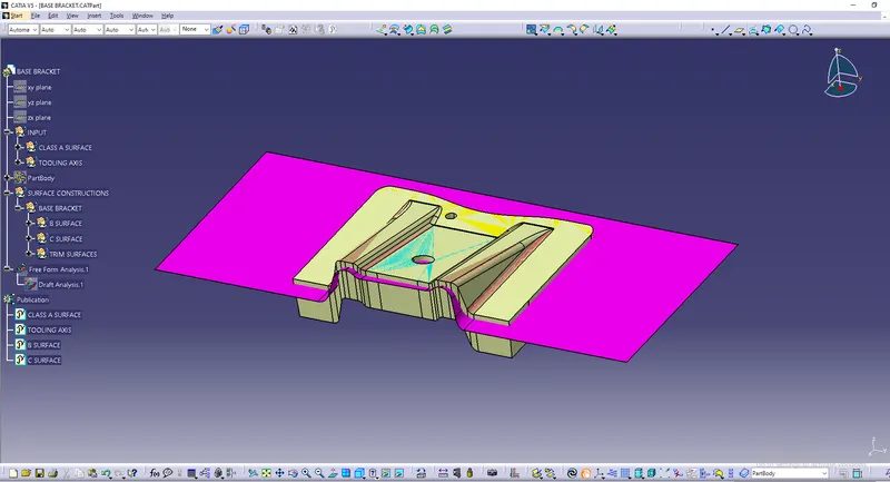
Using the B and C surfaces created a closed surface will be formed by trimming the excess surfaces the surfaces will be converted into a solid model using Closed surface option
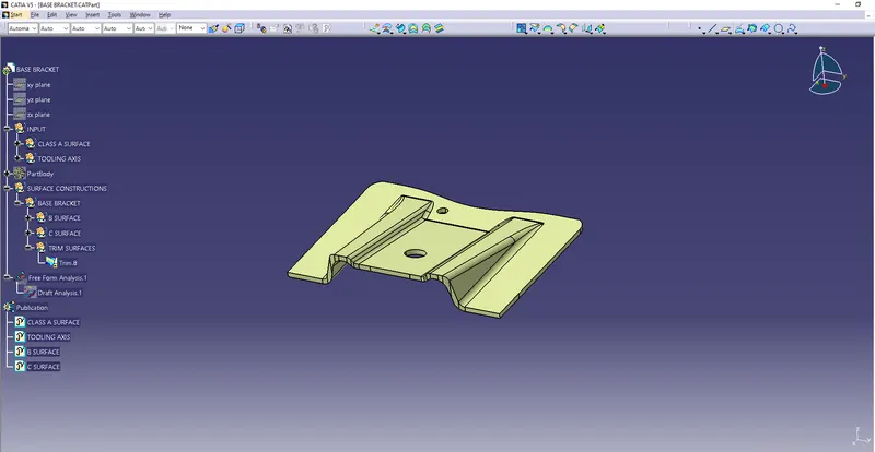
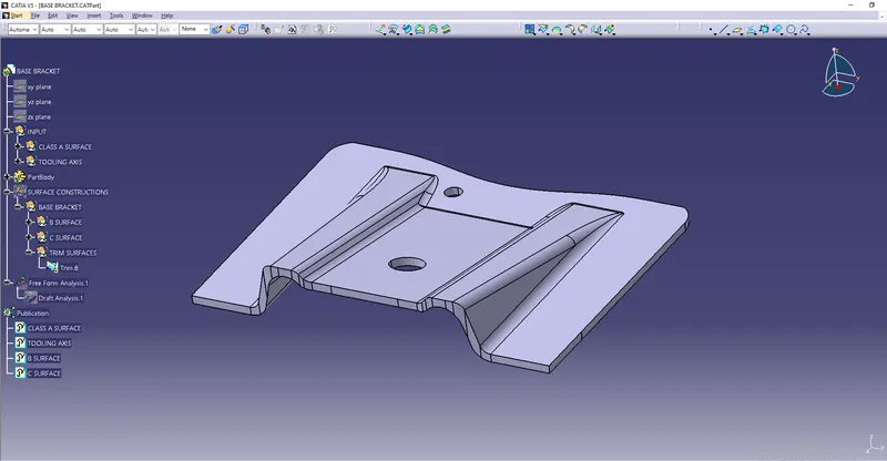
DRAFT ANALYSIS FOR PLASTIC COMPONENTS
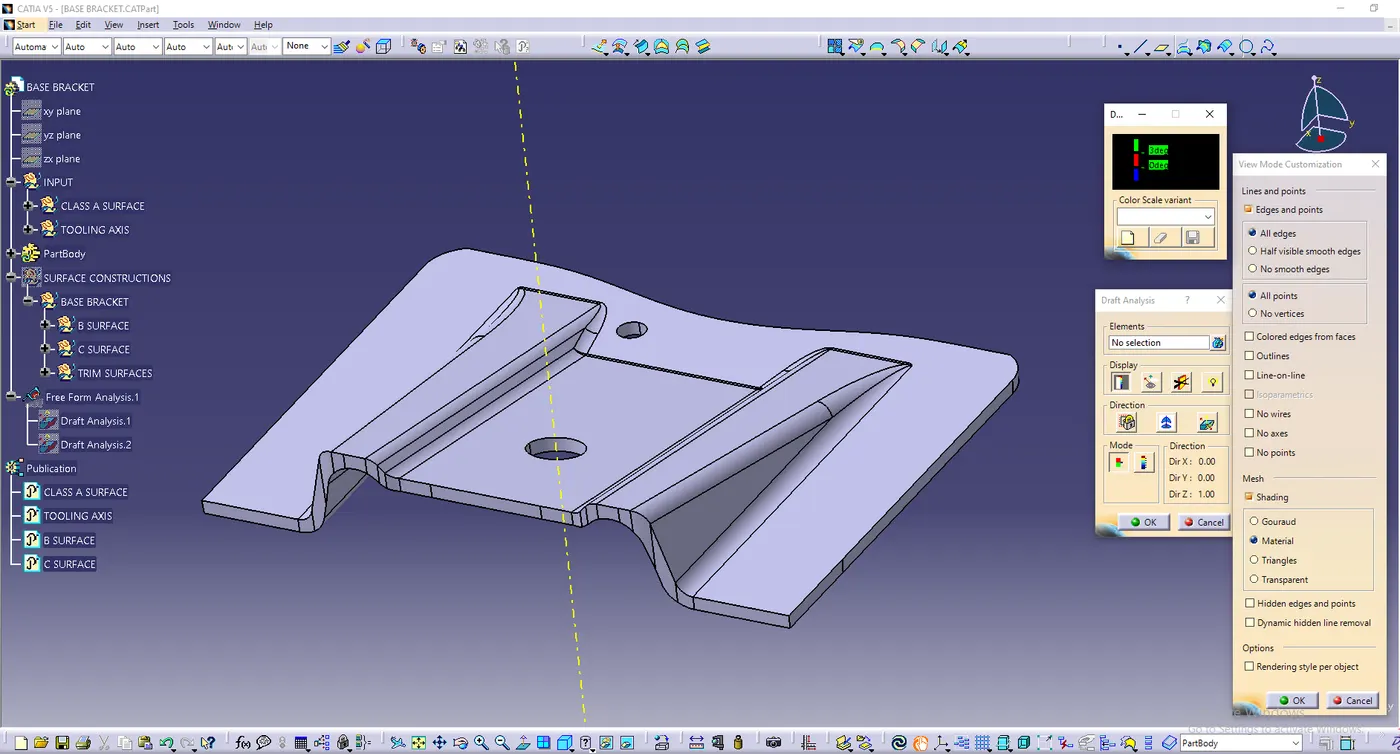
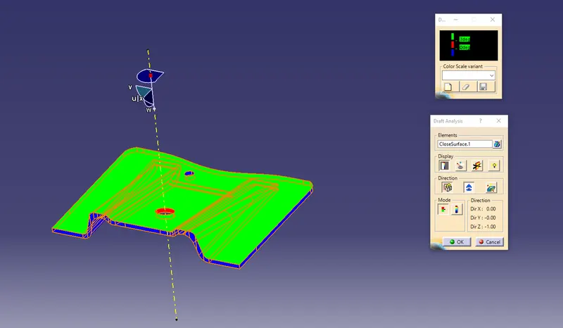
Screenshots of the solid model with the proper color code of the draft angle in various orientations (Isometric, Front, Side, and Top View)