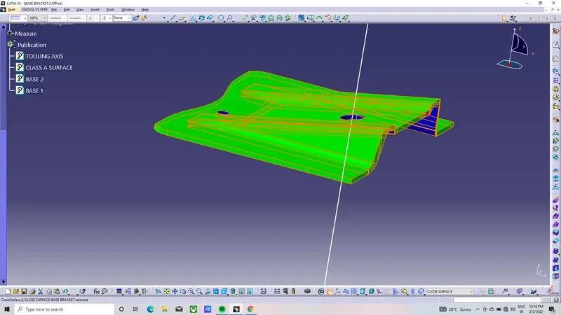
Week 8 - Challenge 2 - Base Bracket Design
AIM:
To determine the Base Bracket Plastic component through the given Class-A surface. To begin with, the tooling axis for the given Class-A Surface should be created meeting the requirements of the draft angle and at the end perform the Draft analysis on the model.
PROCEDURE:
The First method in this base bracket the method is to set the tooling axis on the diagram.
First create the bisector on the diagram and make point on the inclined on the bisector of left and right side
After creating the ponit draw the line on the right point and join the two point as well this method is follow on the left side also.
Then create the centre point on the object and make the point
After creating the centre point and draw the centre from the bisecting line is show in the figure
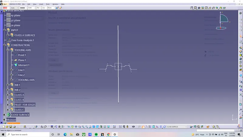
After creating the centre line mark as tooling axis and placed on the new geomentric part
The next method is to create the extract from the given class a surface. class a surface showes in the figure
First extract the right side rib on the class a surface show in the figure
And untrim the extract and also extrapolate because of the extra surface we use the extrapolate tool
And then hide th extract only visible on extrapolate is shows in the figure
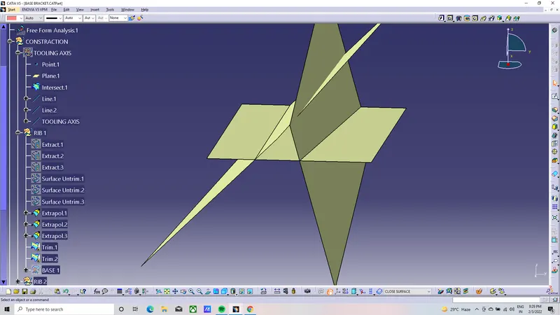
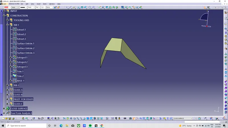
This is rib on final trim process is done and then offset the trim in to 2.5 mm down
And this method is follow on the another ribis called as rib 2 atha picture show in the figure
and joint the two rib and base and side access also trim and joint the class B
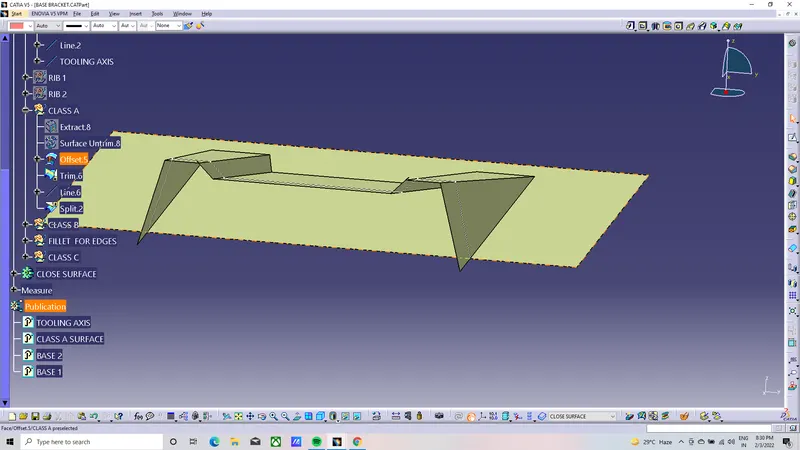
THE FINAL OUTPUT OF CLASS B IS SHOW IN THE FIGURE
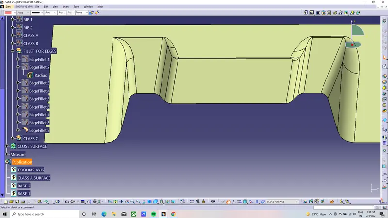
After finish the class b surface and tnem applied thr edge fillet on the side on th diagram
by the edge fillet method of the concept on convex and concave and applied the radius
the final edge fillet diagram is show in the figure 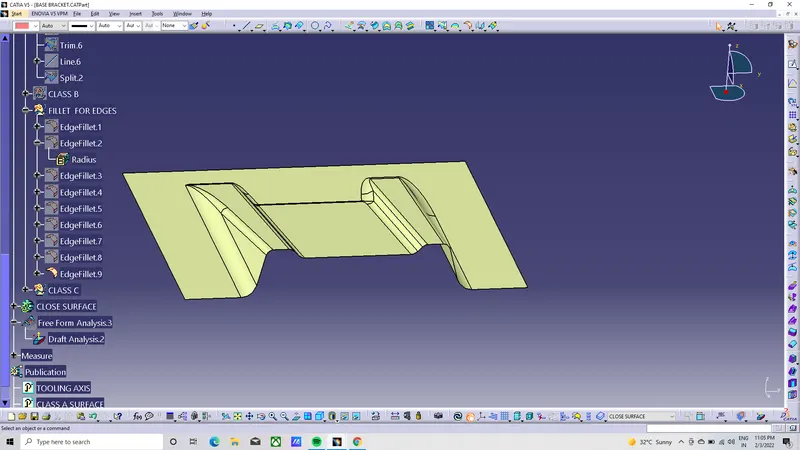
After the edge fillet is then start the class c surface
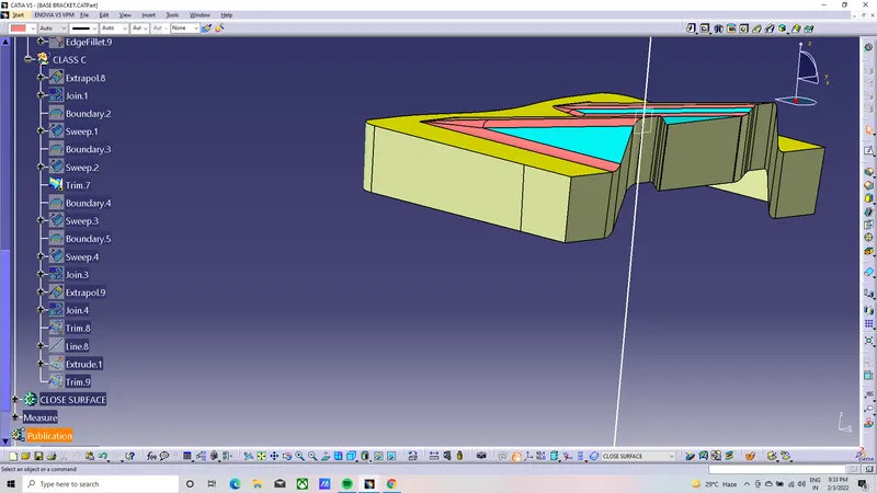
open the class a surface and create the boundary on the surface
and create the swept on the class a surface with the angle of 3 degree with the referance of tooling axis
And the class b surface trim the class A and class B and that is class c is thickness of 2.5mm
and check the boundary on the final part of class a
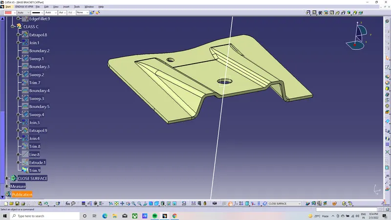
after the creating of classc the next the plastic component is converted in solid in the part design
covert work method 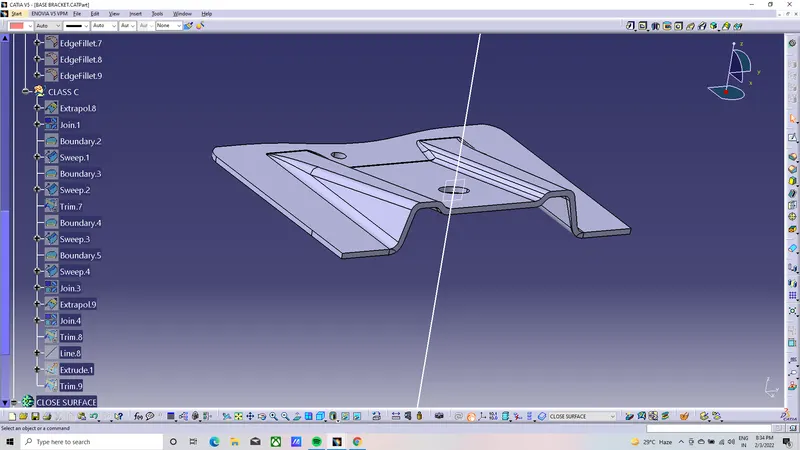 the generative shape design into part design and select the close surface tool and applied on the surface on the diagram and result shown in the figure
final the analysis method
CLICK THE TOOLS BAR ON THE TOP AND CHOOSE THE ANALYSIS IN THE feature draft analysis