Week 8 - Challenge 2 - Base Bracket Design
Report:
Base Bracket Design
Introduction:
In this project we conduct a Draft analysis on the provided Class A surface of Bracket in Catia V5 and create a solid model of the bracket using Class B and Class C surfaces.
Draft Analysis:
The Draft analysis is used to check the manufacturability of the given part. The analysis provides crucial data regarding the draft angle given to the part, i.e. if the angle satisfies the standard draft angle required on products for ease of manufacture during operations like injection molding.
The Draft angle is measured along the tooling axis. This angle allows the manufactured part to be released from its mold with ease and without friction/grinding against the mold surface. The standard draft angle usually provided is between 3-5 degrees.
Tooling Axis:
The tooling axis provides the direction in which the part is to be produced. The tooling axis is determined by taking into account the various features on the product such as holes, embosses, flanges, tapers etc.
The method to determining a tooling axis is by taking an intersection between the surface and a selected direction. The intersection creates a 2D section of the part. Then after determining the crucial features, we take a bisecting line between the selected feature section lines. This gives the tooling direction along the selected plane. Thus, repeating the process in other directions, we get two tooling direction lines and taking a bisector between these direction lines provides us with the tooling axis of the part.
Tooling axis of Base Bracket:
- Tooling axis:
Since there is only one feasible direction for tooling the bracket design, we get the tooling axis by taking a bisector of draft surfaces intersected on the selected plane.
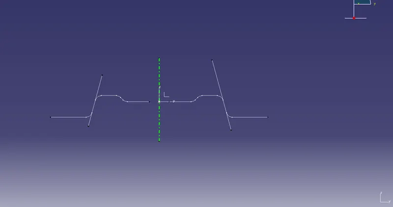
Draft analysis on the Base Bracket:
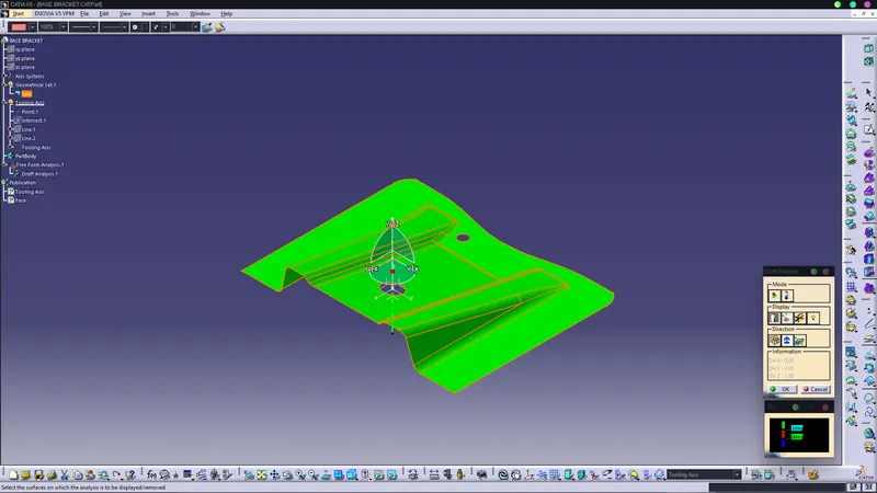
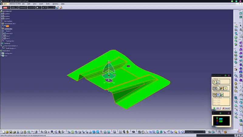
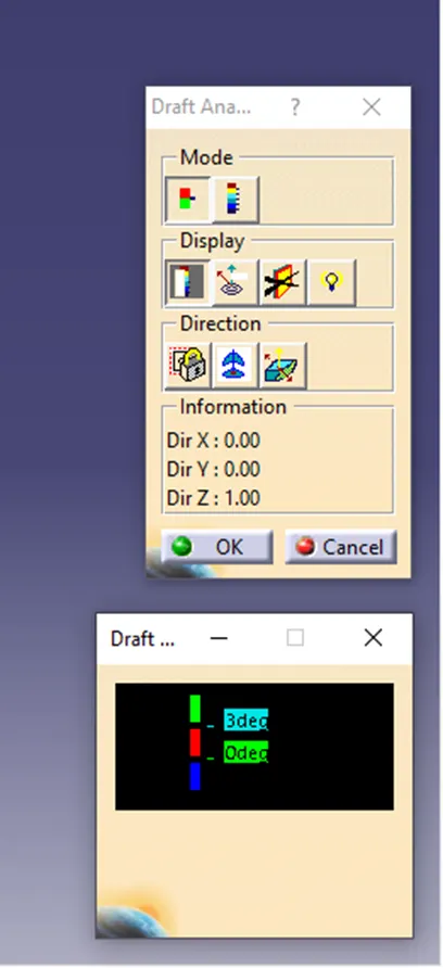
For the analysis, we input the tooling direction by placing the compass on the tooling axis and then selecting the part. The color gradient panel provides information about the draft angle based on the colors, with green colour being user defined while the red and blue colors are kept as 0 and negative respectively or else the user can define their own parameters for these colors.
Below are the images of the Bracket analysis with the draft angle kept at 3 degrees.
Class B Surface:
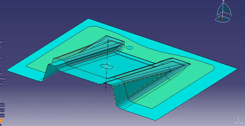
The class B surface is an offset of the class A surface with the offset distance being determined by the thickness of the actual part to be manufactured.
As Shown below, the highlighted surface below the class A surface is called the class B surface.
Class C surface:
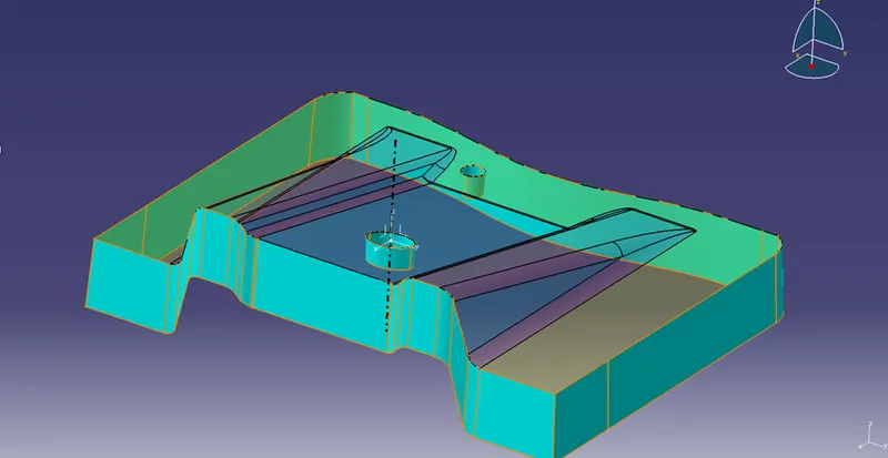
Class C surface is the perpendicular surface to the class A surface, it lies along the thickness of the part.
Surface C includes features like draft angle surface, hole surfaces etc.
As shown below the highlighted surface is the Class C surface.
Closed Surface:
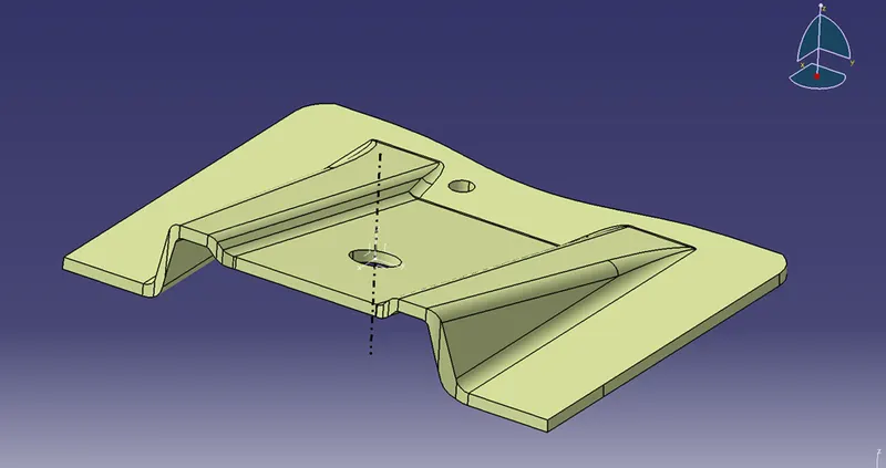
After creating the class B and class C surfaces, they are trimmed and joined with the parent Class A surface to create a closed surface of the part. The closed surface is then used to create the actual part body using solid features.
Shown below is the Closed Surface of the base bracket design.
Solid Body:
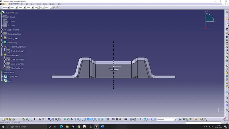
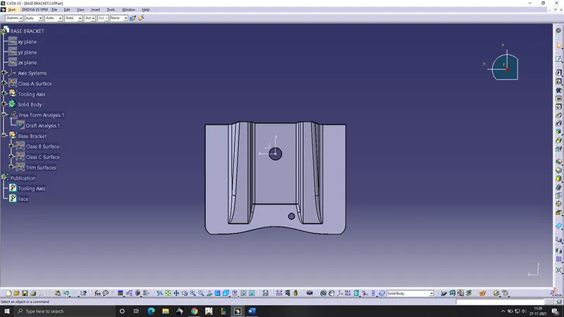
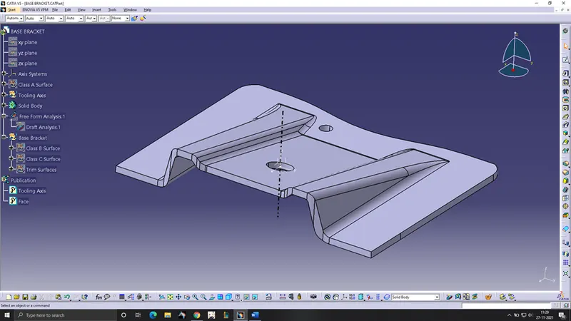
Solid Body can be created from the surfaces using various methos like closed body method or thicken surface method. The solid body represents the actual part body which will be manufactured.
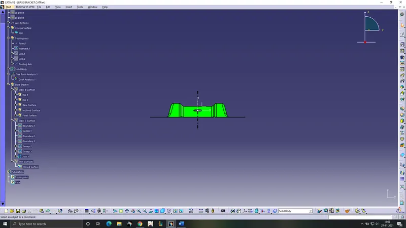
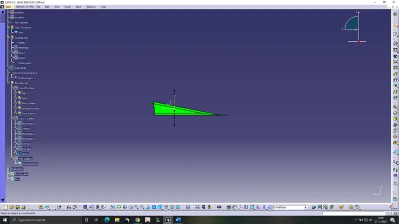
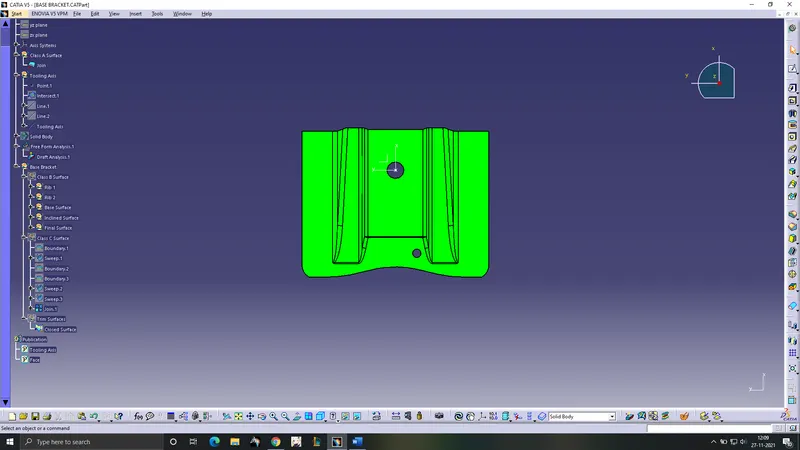
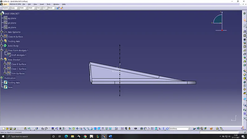
Shown below are some views of the Part body of the base bracket.
Front view:
Top view:
Side view:
Isometric view:
Draft analysis with color codes: