Week 8 - Challenge 2 - Base Bracket Design
Objective:
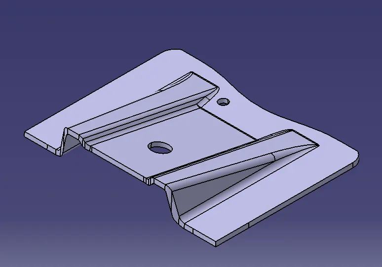
Create the Base Bracket Plastic component through the given Class-A surface. To begin with, the tooling axis for the given Class-A Surface should be created meeting the requirements of the draft angle and at the end perform the Draft analysis on the model.
Answer:
1) Draft Analysis
Draft analysis is done to ensure that the designed part is manufacturable based on the draft conditions applied. It is done to ensure the proper ejection of the component from dies(for metals) or molds(for plastics). The basic idea is to ensure that the tooling axis has to be created in such a wat that it has no parallel surface profiles of the component so that the ejection of the components can be ensured . Tooling axis is the axis along which cavity and core are closed and opened .
2)Procedure for creation of tooling axis using bisecting method .
Step 1: Import the model and check for surface continuity and connectivity using Join tool .Ensure there is no surface gap
Step 2: Insert a geometrical set . Create a point at the center of the circular profile using point tool. Look for suitable axis to create a tooling axis so that all faces clear tooling . In this case Z axis is most suited to create tooling axis . create a line using point & direction option along Z axis and name it as reference tool axis
Step 3: Create an axis system without current option ticked .It should allign with vehicle zero .
Step 4: Use intersection tool to create 2 lines by selecting a suitable plane(zy) as first element and component as second element . Now increase the length of feature or surfaces we have doubt will cause problems in draft analysis using lines option.
Step 5: Create a new line by bisecting these extended lines and center point . Allign the line in required axis direction . This is our required tooling axis . Name this as Tooling axis .
Procedure to check for Draft analysis
1)Once the tooling axis is created , publish it and the component using Publication from tool option .
2)Insert Feature draft analysis option from insert tool bar
3) Change the view option to customize view parameters and click om material option under shading .
4) Now click on the axis option from Draft analysis tools , allign it with tooling axis and click on lock option to lock it .
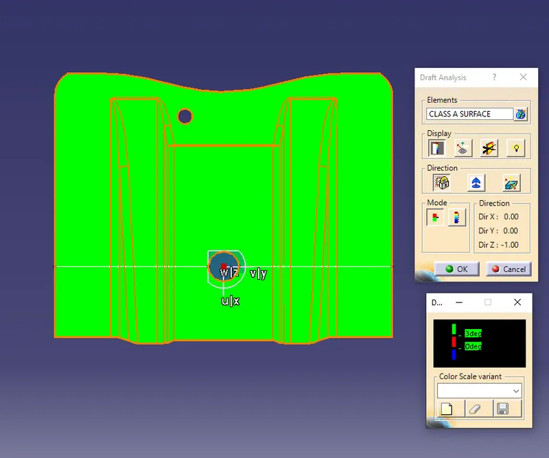
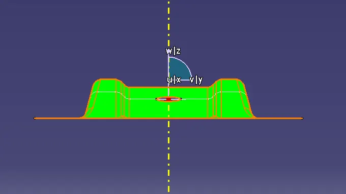
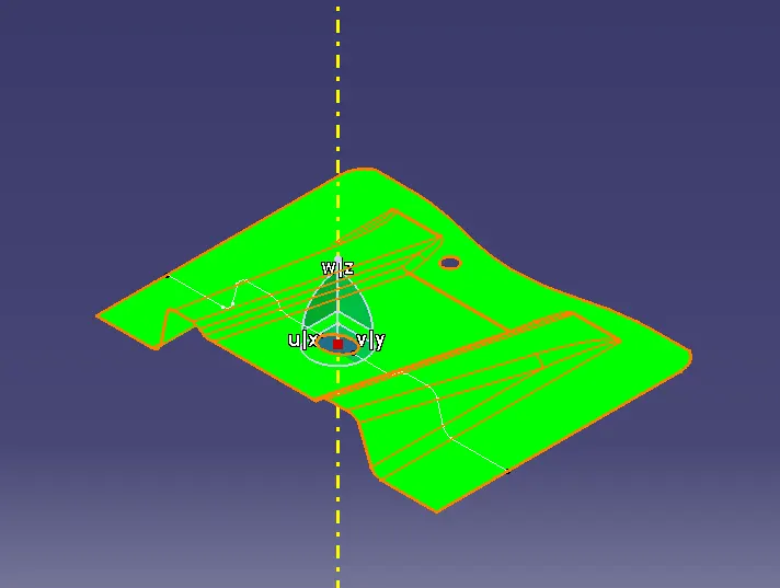
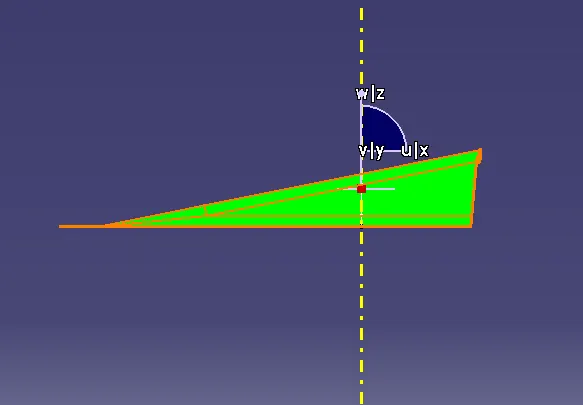
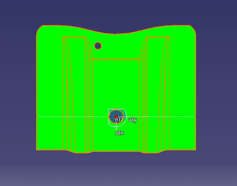
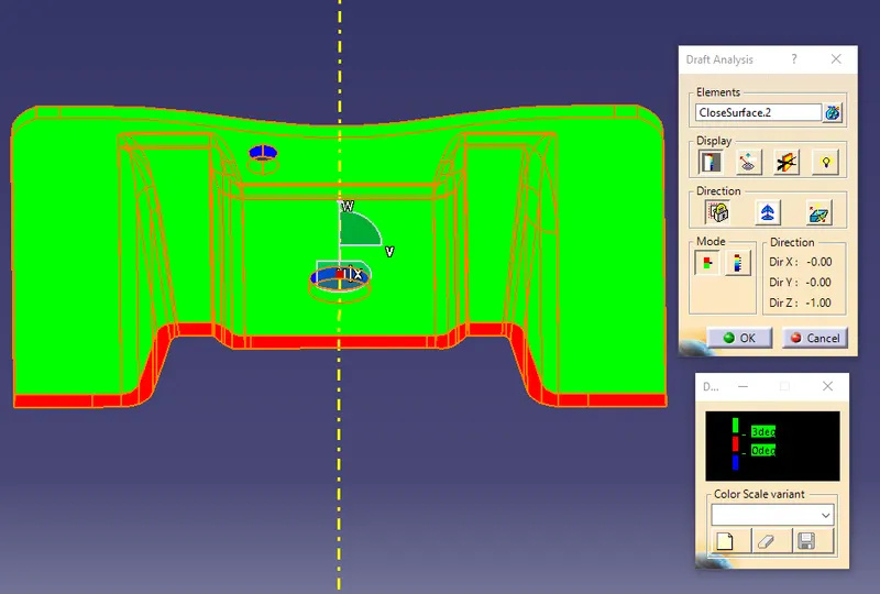
5) Change draft angle value to 3 degree . Click on quick analysis mode to display feature according to given color scale . Check from all views to ensure the draft analysis is cleared . Click ok to complete the Draft analysis mode.
Draft Analysis for CLASS A
Draft Analysis for Solid part
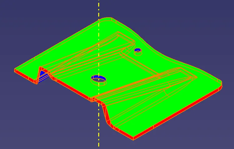
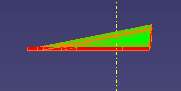
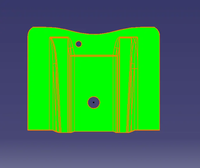
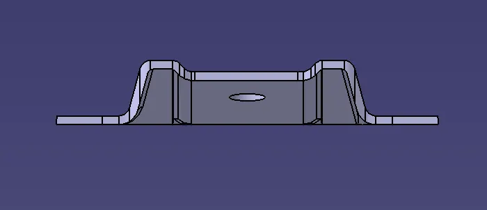
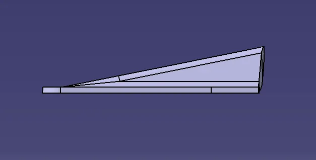
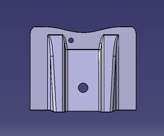
Final Solid Part images