Week 8 - Challenge 2 - Base Bracket Design
Week 8 - Challenge 2 - Base Bracket Design
Aim: To create the Base Bracket Plastic component through the given Class-A surface. The tooling axis for the given Class-A Surface(shown below) should be created meeting the requirements of the draft angle and at the end perform the Draft analysis on the model.
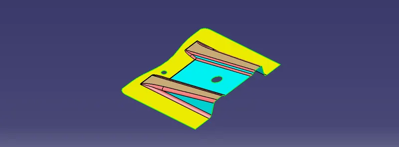
Image 1 Given Class A Surface
Theory:
Draft in Mold:
Draft is the amount of taper for the molded or casted parts perpendicular to the parting line. It is measured in degrees or mm/mm. It helps account for thermoplastic shrinkage, a practical reality of the injection molding process for most materials. An example of draft in mold is shown below.
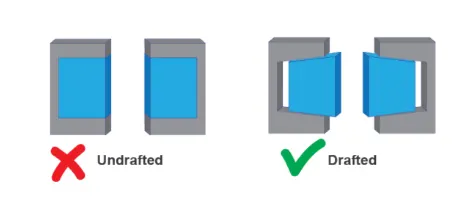
Image 2 Draft in mold
When no draft is designed into the part, problems can come from friction and vacuums. These issues can damage both your part and even your mold in extreme cases. These problems are a direct result of having insufficient draft. Because plastic shrinks as it cools, portions of the part may pull away from the mold while others grip the core. If there is no draft angle that allows a simple push from the ejector pins to pop the part out of the mold, the part’s surfaces will often drag along the mold as it is being ejected. This friction between the two surfaces can cause scratches or gouges in your part and affect the appearance. This is particularly troublesome if your part is being molded with a surface finish or texture. The friction will scrape away texture and leave you with many rejected parts.
In addition to friction, no draft presents the possibility of a vacuum forming during ejection. If the sides of a feature cannot release from the mold, the ejector pins may push on the section until the vacuum becomes so stressed that the part may bend, break, or warp by the time it is pushed out. The alternative is that the part becomes stuck in the mold if the ejector pins are not strong enough to overcome the vacuum. A higher ejection force would be needed to remove a part without draft, which means the part would need to cool longer before it can be ejected successfully. This increase in cycle time and the likelihood of having more rejected parts overall will drive up your production costs.
By adding draft angles to your design, you can avoid these problems and lower the cost of production. Draft will allow parts to release from the mold with ease, which will result in better cosmetic finishes and fewer rejected parts. In addition, draft can help you avoid costly elaborate ejection setups.
Draft Analysis:
Tooling Axis: The Tooling Direction is basically the direction that the mold pulls apart. The mold is built in two separate pieces, Cavity side and Core side. The Core pulls apart from the Cavity and that is the Dyeline or the Tooling Direction. The axis of the Tooling Direction is called Tooling Axis.Draft Analysis is done on the CAD part to detect if the part drafted can be easily removed or not. This type of analysis is performed based on color ranges identifying zones on the analyzed element where the deviation from the draft direction at any point, corresponds to specified values.
Procedure:
Following things are to be done while creating the Base Bracket Plastic Component through the given Class A Surface.
- Creation of Tooling Axis
- Performing Drafing Analysis on the given Class A Surface with respect to the created tooling axis
- Creation of the Class B Surface
- Creation of Class C Surface
- Joining all three surface to form Closed Surface
- Performing Draft Analysis on the Closed Surface
- Creating Solid using the Closed Surface
1. Creation of Tooling Axis:
Step 1: Creating Dummy Tooling Axis
Initally a dummy tooling axis is created according to the Class A surface. Features of the Class A surface, such as Holes, Fillets, chamfers etc, is considered while creating the dummy tooling axis.
In the given model, there are two holes and most of the surface is flat. Hence, a dummy tooling axis is created with respect to the flat surface . To create a dummy tooling axis
Create a point on the center of hole> Create an axis on that point having a plane parallel to the flat surface> Create a line point-direction- select the circle center, select z axis as direction(Refer the image below)
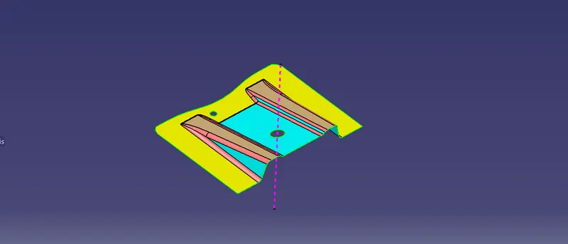
Image 1.1 Dummy Tooling Axis
Step 2: Create Tooling Axis
To create Tooling Axis for the given component
Create an Intersection curve between the xz plane and the class A surface> Create a Line using the two points of the side walls of the base bracket on both sides> Create a new bisecting line between the two newly created lines> This will be the Tooling axis.(refer the image below)
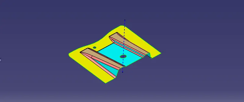
Image 1.2 Tooling Axis
2. Performing Drafing Analysis on the given Class A Surface with respect to the created tooling axis.
Drafting analysis is done on the Class A surface to verfiy whether the Tooling Axis Created is correct or not. To perform drafting analysis
Insert>Analysis>Feature Draft Analyisis> Select the Class A Surface> Set the Draft Angles> Fix the Axis on to the Tooling axis(refer the below image)
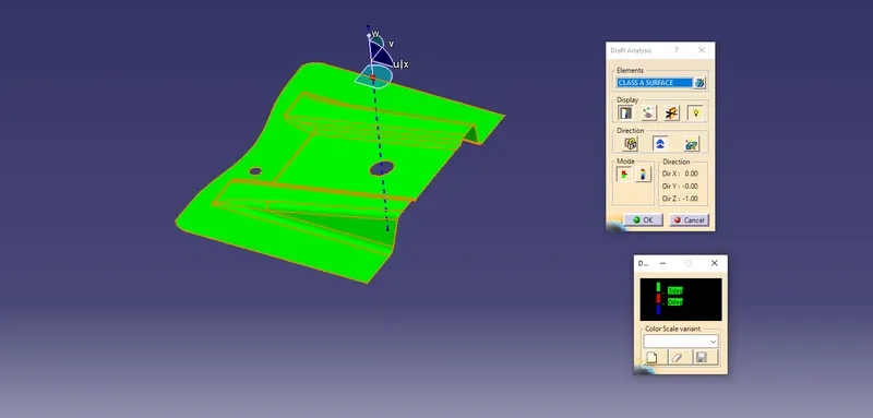
Image 2.1 Draft Analysis on Class A surface
3. Creation of the Class B Surface
Surface Offset Method is used to create Class B Surface. In this method Flat surface on Class A is extracted and offset to specified thickness> Extrapolated in all Direction> Trimmed to get Class B Surface> Fillet is add wherever neccessary(refer the below image)
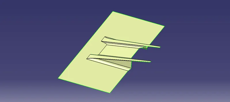
Image 3.1 Class B Surface
4. Creation of Class C Surface
To create class C surface, The boundary of Class A Surafce extruded using Spline tool(Draft Direction)(refer the below image)
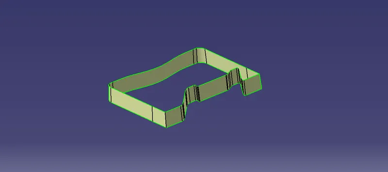
Image 4.1 Class C Surface
5. Joining all three surface to form Closed Surface
Joined Class A, Class B and Class C surface using Trim Tool.(refer the below image)
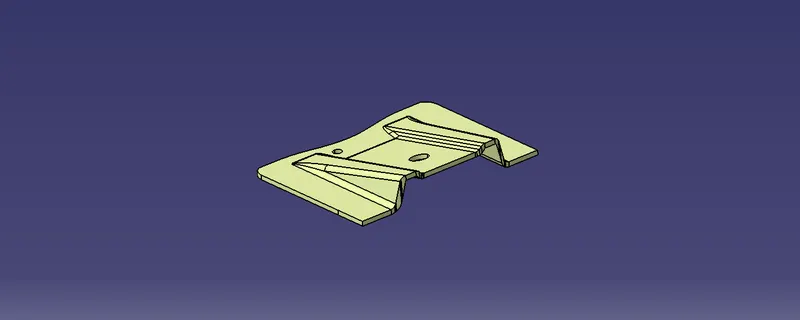
Image 5.1 Closed Surface
6. Performing Draft Analysis on the Closed Surface
Draft analysis is performed on the Closed Surface.(refer the below image)
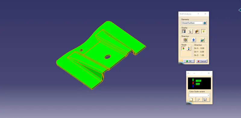
Image 6.1 Draft Analysis on Closed Surface
7. Creating Solid using the Closed Surface
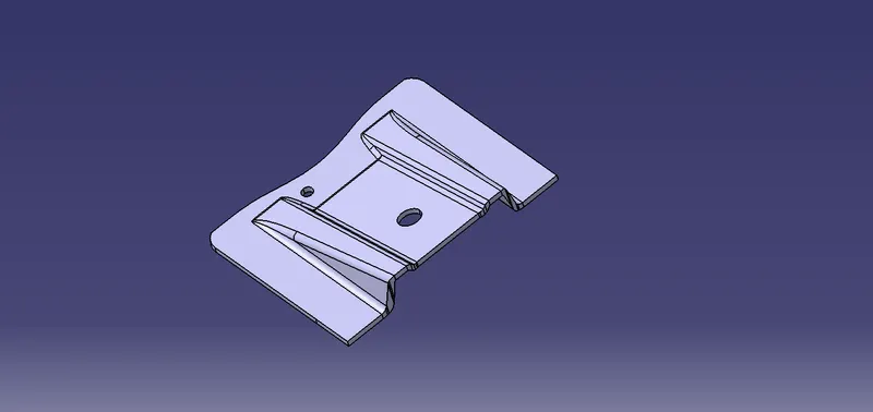
Image 7.1 Solid Creation using the Closed Surface
Complete Model:
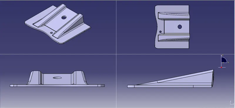
Model Tree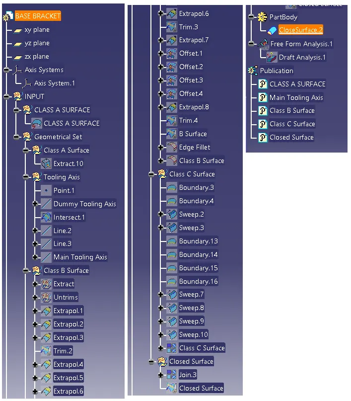
Conclusion: Performed following operation to create Base Bracket from the given Class A Surface
- Creation of Tooling Axis
- Performing Drafing Analysis on the given Class A Surface with respect to the created tooling axis
- Creation of the Class B Surface
- Creation of Class C Surface
- Joining all three surface to form Closed Surface
- Performing Draft Analysis on the Closed Surface
- Creating Solid using the Closed Surface