Week 8 - Challenge 2 - Base Bracket Design
Base Bracket Design
Introduction
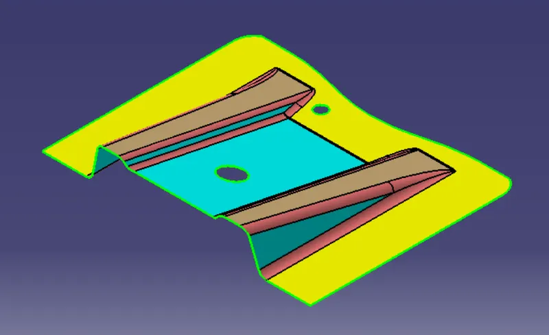
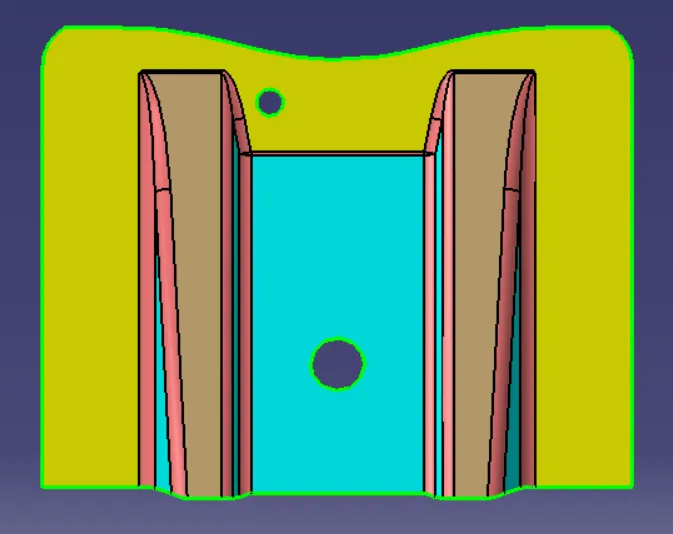
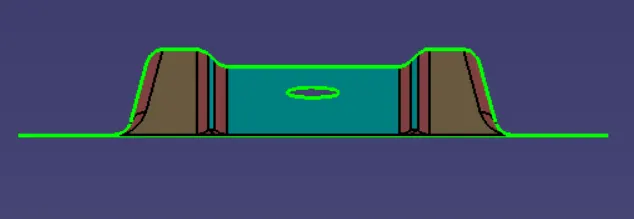
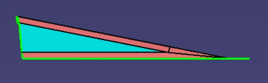
Create the Base Bracket Plastic component through the given Class-A surface. To begin with, the tooling axis for the given Class-A Surface should be created meeting the requirements of the draft angle and at the end perform the Draft analysis on the model.
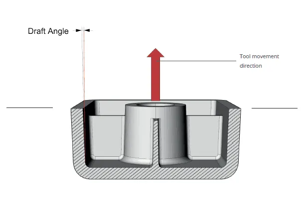
Draft Angle
The draft angle is the amount of taper for molded or cast parts perpendicular to the parting line. It can be measured in degrees or mm/mm (in/in).
Tooling Direction
Tooling Direction is the main consideration for plastic parts and mold parts because it defines the movement of the mold part and the possibility of the part coming out from the mold part.
Tooling Axis
The axis along which the mold or core and cavity opens.
The draft analysis within CATIA V5 will help you quickly gather the draft angle on multiple surfaces without the need for tedious manual measurements. The Draft Analysis allows the user to easily analyze a part for proper draft angle.
Importance of Drafting
When developing parts for plastic injection molding, applying a draft (or a taper) to the faces of the part is critical to improving the moldability of your part. Without it, parts run the risk of poor cosmetic finishes and may bend, break, or warp due to molding stresses caused by the plastic cooling. Equally important, an absence of a draft may prevent parts from ejecting from the mold, damaging not only the parts but possibly the mold itself—a costly and time-consuming detour.
Mode Option
The mode option lets you choose between a quick and a full analysis mode. These two modes are completely independent.
The default mode is the quick mode. It simplifies the analysis in that it displays only three color ranges.
Class A Surface
- Visible surface and aesthetic look
- Surface with textures
- Surfaces provided by customer(OEM)
- Don't have any features like(rib, snap, bosses, etc) on class A surface.
- Class A surface is made from scanned data with different software like alias etc.
- Surfaces which is having CURVATURE CONTINUITY IS CALLED class-A.
Class B surface
- Invisible Surfaces.
- Surface mostly don't have textures
- The surface needs to be created according to the class-A surface.
- Having all features(Rib, boss, snap, etc) in B-side surface only.
- Surfaces which is having TANGENT CONTINUITY IS CALLED class-B
Class C Surface
- Class C finish allows more imperfections than Class A or B.
- It is often specified for interior surfaces not readily visible, surfaces that will be covered by another part when assembled, or surfaces that the Customer feels do not need to meet a high cosmetic finish.
- It is used for parts or surfaces which are not viewed after installation or viewed only for service.
- The distance between each point of the edges of two neighboring patches is no more than 0.05 mm.
- The angle between the tangents to the surface on the edges of two neighboring patches is no more than 30’ (0.5◦).
- Shape tolerance is not applied.
Draft Analysis of Base Bracket
1) Connectivity Of Surface
After receiving the class A surface model the connectivity of surfaces was checked. It helps to find discontinuity within the surfaces of the model. The Connectivity of the surface can be checked in three different ways
Join Operation
Boundary Operation
Disassemble Operation
After verifying the connectivity of surfaces these operations were deleted.
2) Determining the Tooling Axis
The Tooling axis is the axis along which the mold or core and cavity opens. The tooling axis for a model has to be decided so that no additional works are needed on it which helps to reduce the cost.
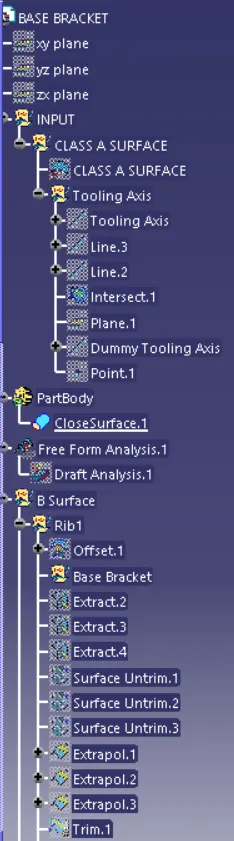
a)A dummy tooling axis is created along the z-axis after analyzing the model. An axis system is created at that dummy tooling axis.
b)Intersection operation is used to get the intersection between the YZ axis plane and the model.
c)Extended Lines are created in the intersection sketches where problems in terms of draft angle may occur.
With the extended lines as reference bisecting lines were made on the class A surface.
d)That bisecting line has been named Tooling Axis. And it is published in the end.
3)Draft Analysis
a)View parameters are customized to Material mode.
b)Insert --- Analysis --- Featured Draft Analysis
c)Compass is moved to Tooling axis. It is locked in that position.
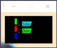
d)In Quick analysis the range of green color is changed to 3 degrees.
The Green Colour has rafted Walls above 3 degrees.
The Blue Colour has drafted walls 0-3 degrees.
The Red Colour has negative angle drafted walls.
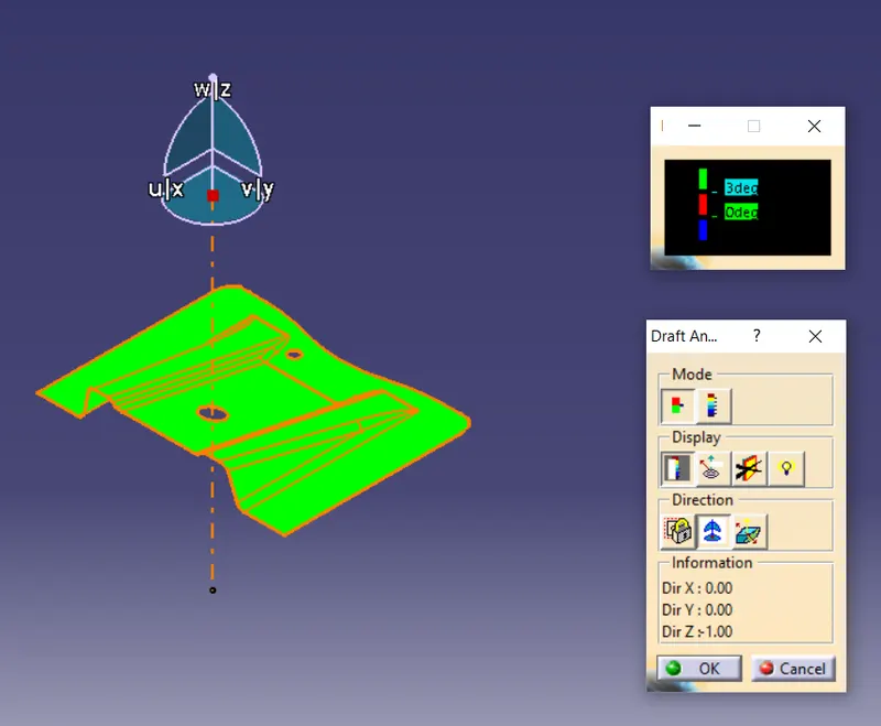
Creating Base Bracket Plastic component from Class A Surface
Creating Class B surface
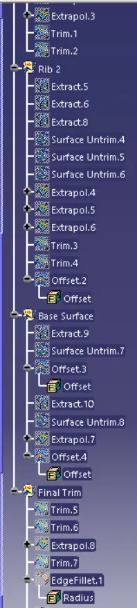
Starting From Ribs, The surfaces of ribs are extracted, Then surfaces are untrimmed and extrapolated to get intersections between those surfaces so that they can be trimmed to obtain Ribs.
After Ribs being created the other surfaces of Class A surface are extracted, untrimmed, extrapolated, and trimmed in the end to get the B Surface. Edge Fillets are added to get the finished B Surface.
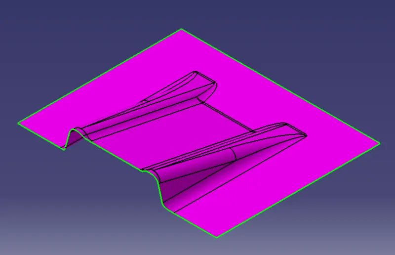
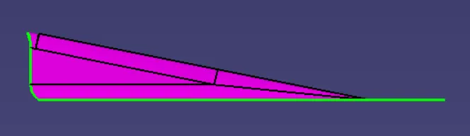
Creating Class C Surface.
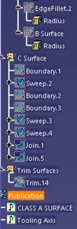
The boundary of the Class A surface and the holes are obtained. Sweep is created from the boundary along the inside draft direction. The Sweep of the hole and surface are joined together.
Class C surface is finally obtained by trimming the obtained surface with the Class B Surface.
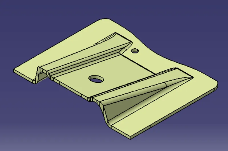
A closed Surface is applied to get the Base Bracket Plastic component.
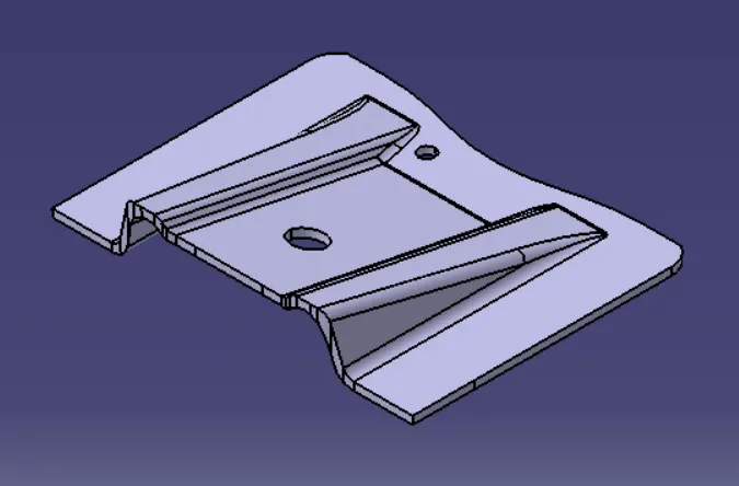
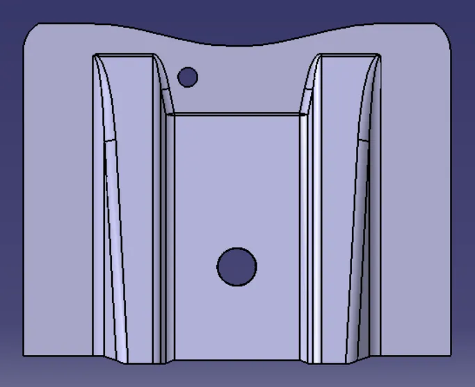
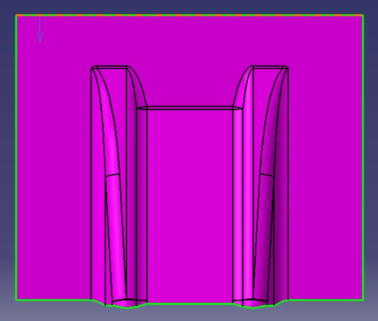
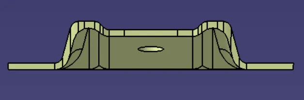
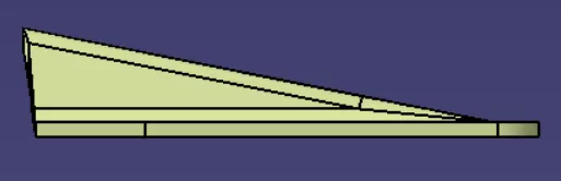
Class A Surface
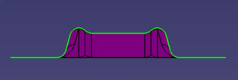
Class B Surface
Class C Surface
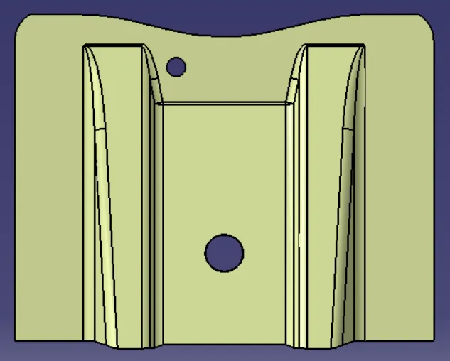
Part Body