Week 8 - Challenge 2 - Base Bracket Design
Ex-02:
Aim:
- To create base bracket with Class A,B,C surfaces along with the draft angle and conert it into solid body.
Tools Used:
- Line
- Point
- Datum Plane
- Edge Fillets
- Intersect
- Draft analysis
- Sweep
- Trim
- Join
Surfaces:
- Creating a bracket we required a class A surface,with this help of A surface we can able to create Class B,C surfaces.This class A surface doesnt have any thickness or Zero thickness surface,For creating a complex shapes and un-uniform thickness this surface can achieved.
- Class B surface will produce the same class A surface with an offset value and maintain some distance on the class A surfaces and it doesn't have any own complex shapes,it will try to recreate the class A surface by mean of offset method.
- Class C surface will join the Class A and B surfaces together and make the surface into solid body.
Tooling Axis:
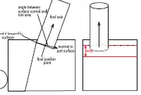
- This axis represent the tool movement that the molded part as to remove from the die with proper condition,lets say if we have an molded part were the support tool is required to hold it,The tool as to be parallel to the part then the tool can be easily inserted to the axis,
- The below fig reperesent the tooling axis were if the axis is 90* then the tool movement will be in same way,in some rare conditions the tool is @ 45* the tooling Axis should be in 45* so that the tool can move along with the axis.
Draft Analysis:
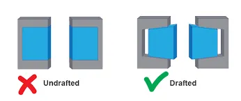
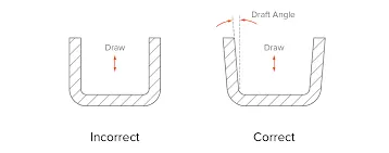
- Draft are very important in molding process a part which is in the die as to be removed ease without defects ,so the draft angles are induced.
- The Below fig explains that if a part is not drafted will get defect during the time of ejection,so to make it easy the draft angles are used for an surface the draft angle should be 3deg and for sheetmetal components the draft angle should be @ 7deg-9deg.
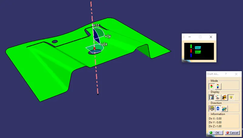
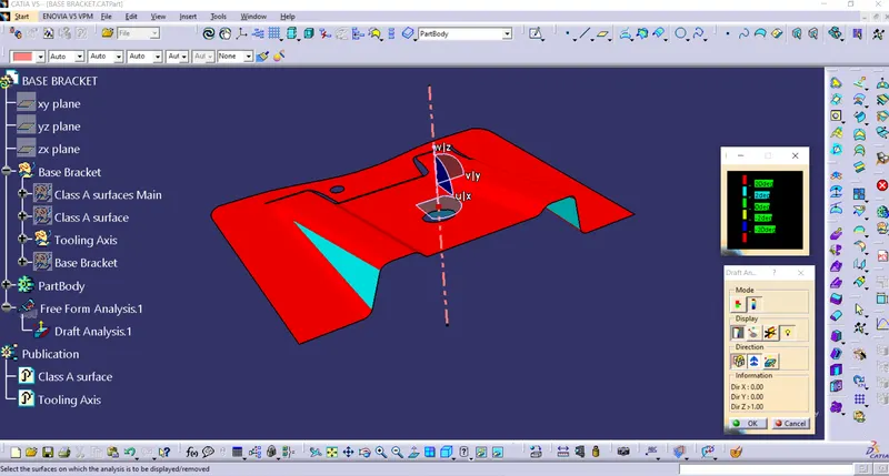
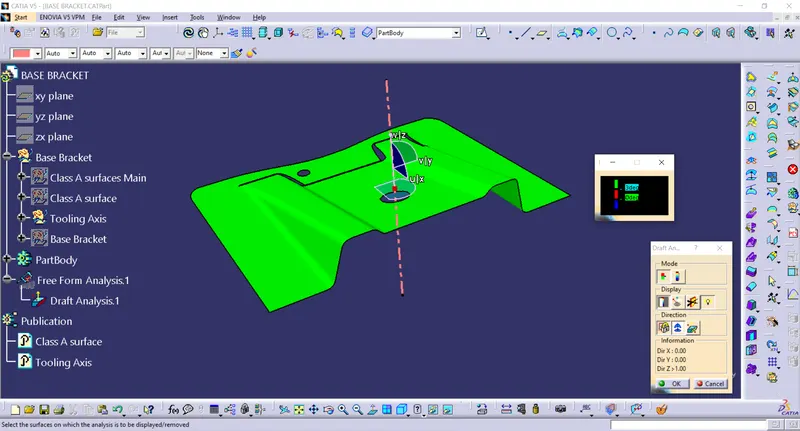
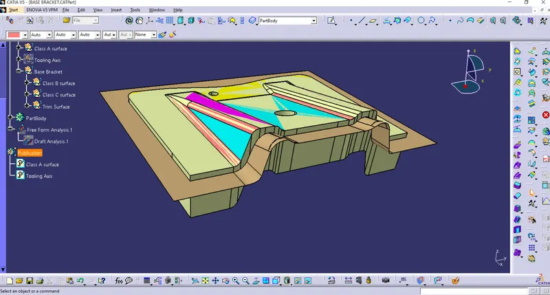
- Draft analysis is the same method which will analysize the part and shows the draft angles,the below fig is the example of draft analysis.
Procedure:
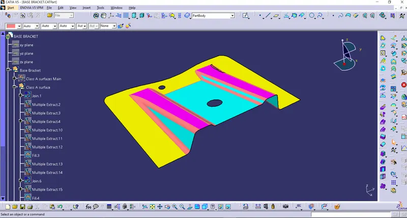
- Create a Class A surface and give some color to various boundries so that will be easy for upcoming works.
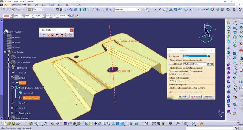
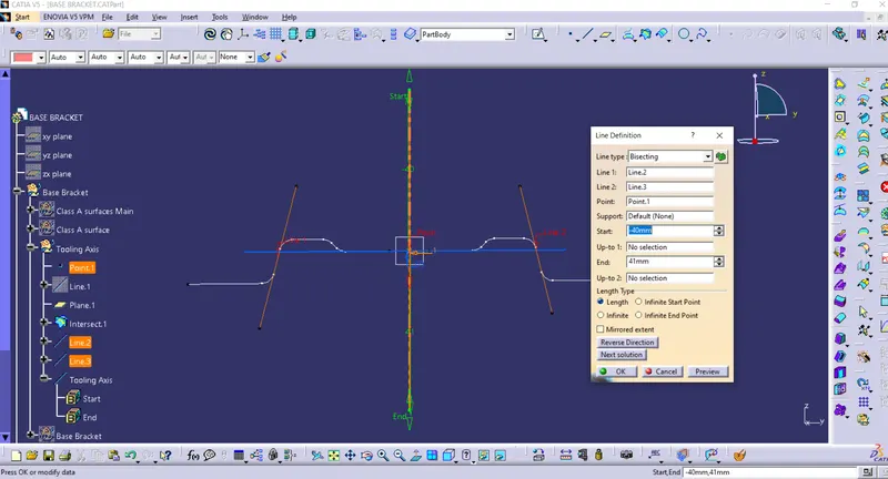
- Create a Tooling Axis by intersecting and bisecting the class A surfaces.
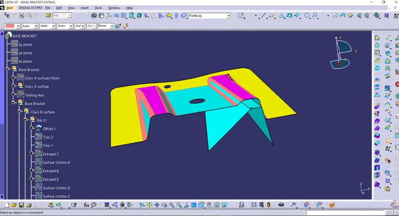
- Create an Extract from the class A surface and trim ,Extrapolate the surfaces and offset it to 2.5mm.Similarly done on both sides.
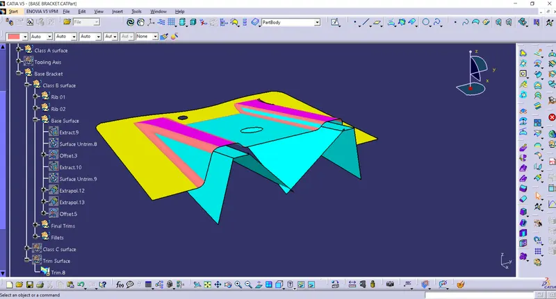
- Create the same extract for the base surface and offset to an value of 2.5mm
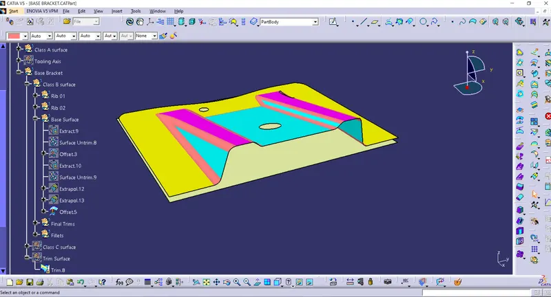
- Finally trim all the surfaces and will get the desired shape on below fig.
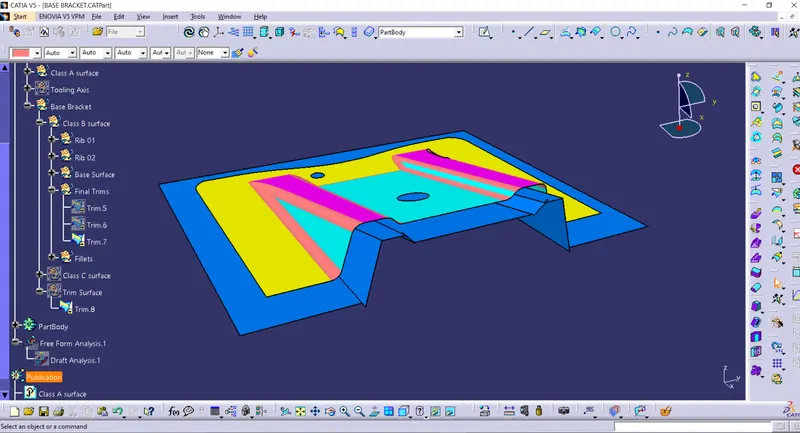
- Create fillets on the edge of the surfaces to finish as a B surface.
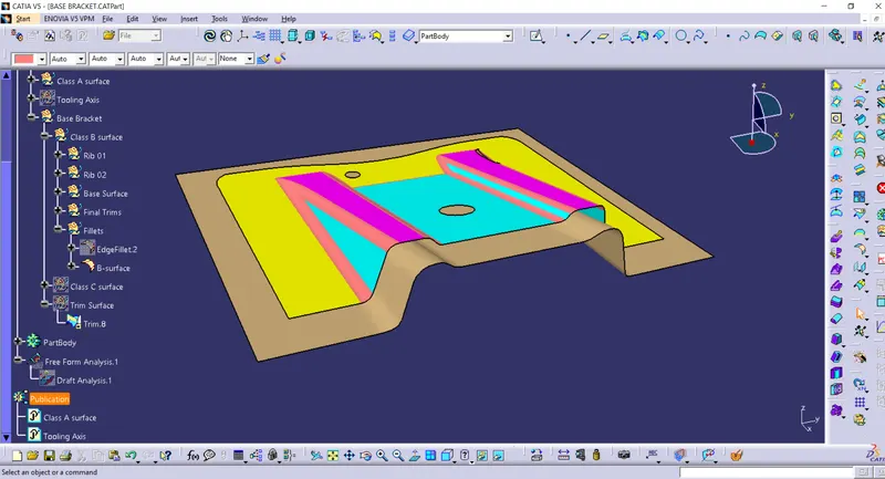
- Draft analysis is made to confirm that the surface is @ 3deg.
- Create a Sweep on the boundry of class A surface.
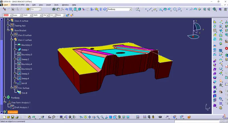
- Join Class A surface along with the sweep using join option.
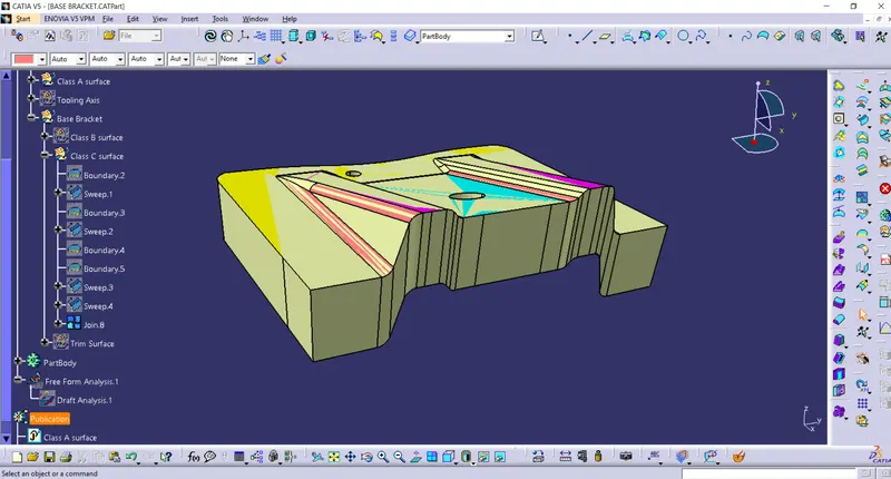
- Trim the Excess surfaces by Class A and B surfaces to get desired thickness.
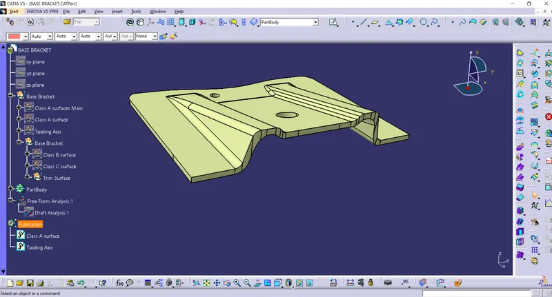
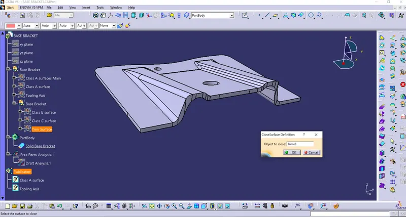
- Finally make the surface solid by using close surface option.
Views:(Isometric,Top,Front,Side)
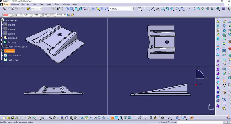
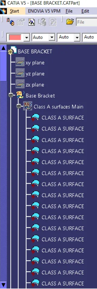
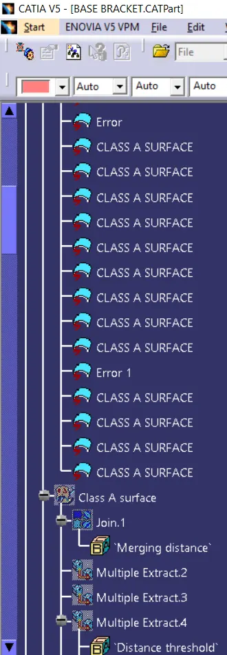
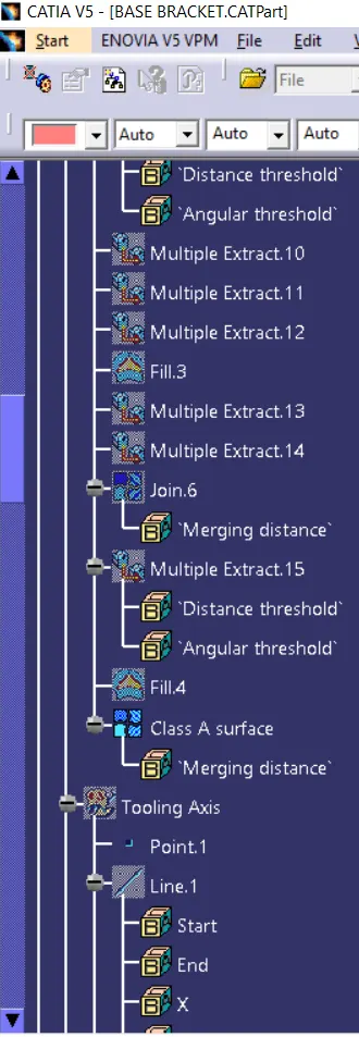
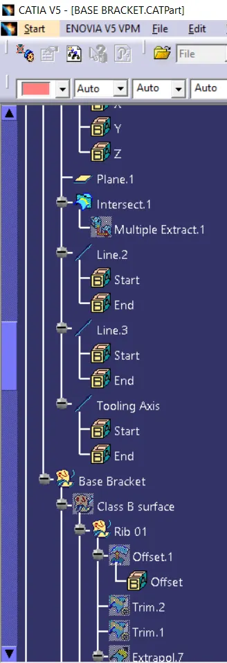
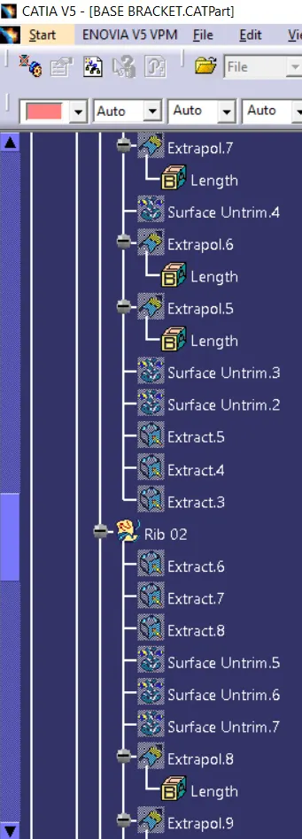
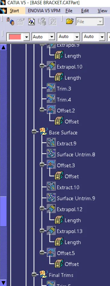
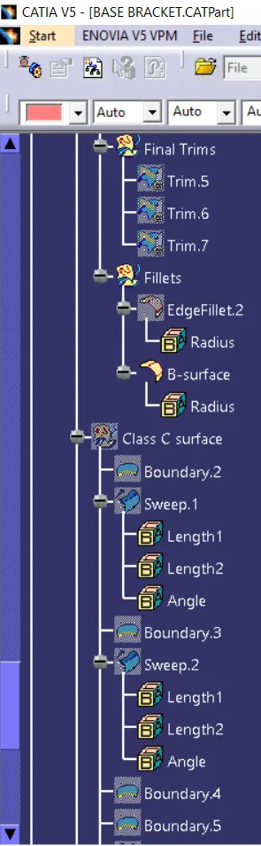
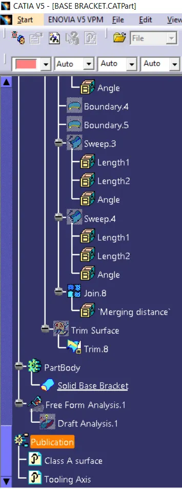
Feature Tree Manager: