Week 8 - Challenge 2 - Base Bracket Design
Automotive Plastic Design using CATIA V5
Week 8 - Base Bracket Draft Analysis & Design - Challenge 2
AIM: Creating the Base Bracket Plastic component through the given Class-A surface with, the tooling axis for the given Class-A Surface and meeting the requirements of the draft angle and at the end perform the Draft analysis on the model.
PROCEDURE FOR DRAFT ANALYSIS:
STEP 1: Ensure there is no gap between the two neighbouring surfaces.
Operations>Boundary>definition>select component
STEP 2: Tooling Axis : Tooling axis is the direction in which mold or core and cavity is opened.
We have to check all possible tooling directions in all the three axes. When we are deciding the tooling axis we have to make sure that all the faces should be visible to that tooling axis, no face should be hidden.
For this component Z axis will be the best tooling axis as we can see all the faces of the component and can be cleared in x and y axis direction.
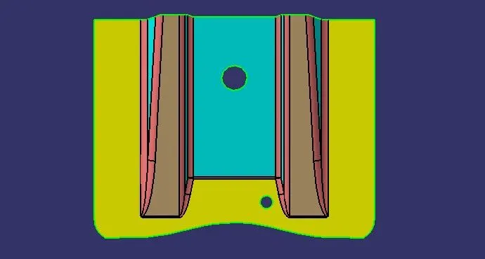
STEP 3: Create a point and extrude a line from it so that we have clarity that we are working in the right direction that is the z axis direction.
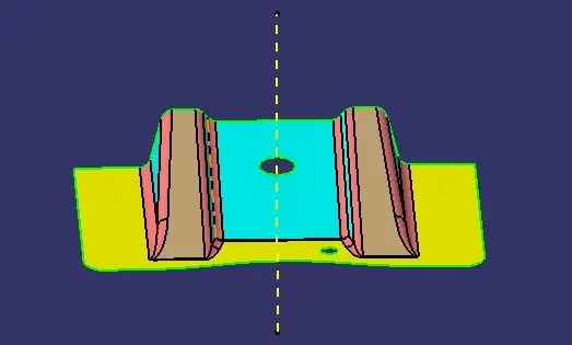
STEP 4: Intersection line along the XZ plane of the component
Wireframe>Intersection>select xz plane>select component
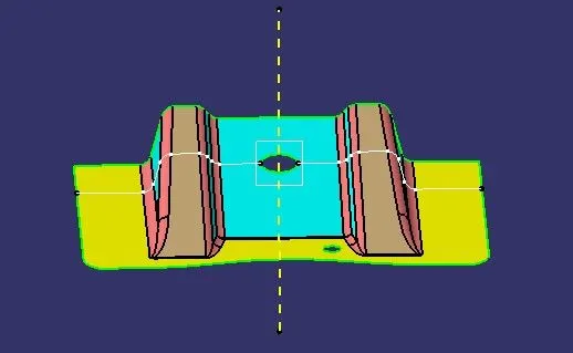
STEP 5: Creating point to point extended line on both sides.
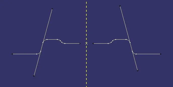
STEP 6: Creating Tool clearing line to X direction by Bisecting line type. Selecting two extended lines and point
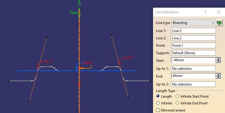
STEP 7: Rename, change color and give thickness to the tooling axis so that it can be easily identified.
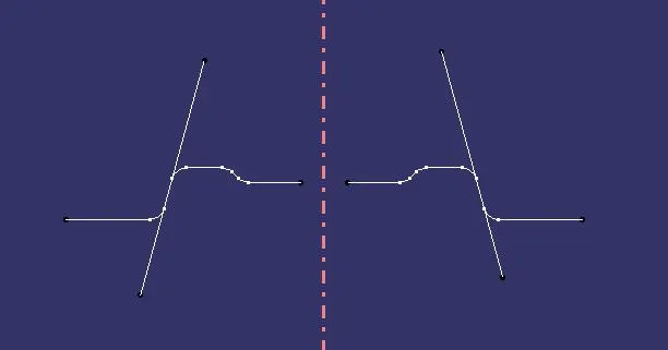
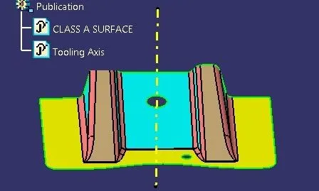
STEP 8: Publish Tooling Axis and Fan Cover Component.
Select this two in model tree>Toolbar>tools>publication>ok
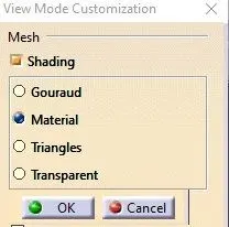
STEP 9: Changing view mode to material.
View mode>view mode customisation>tick material>ok
STEP 10: Giving or Checking Draft Analysis.
Toolbar>Insert>Analysis>Feature Draft Analysis
STEP 11: Drag the compass from the draft analysis box on the tooling axis and place it properly and click on locks so compass will get locked to tooling axis.
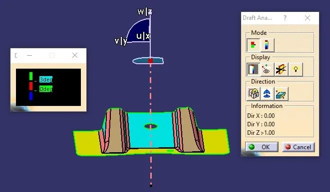
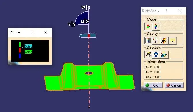
STEP 12: Checking draft angles to suitable degrees.
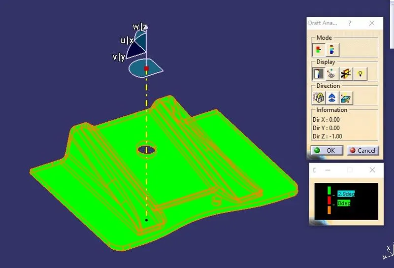
- The Base Bracket should have 3 degrees and it will show green color on the component.
PROCEDURE FOR DESIGN:
STEP 1: Extracting Surfaces
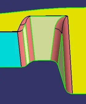
STEP 2: Untrim Surfaces
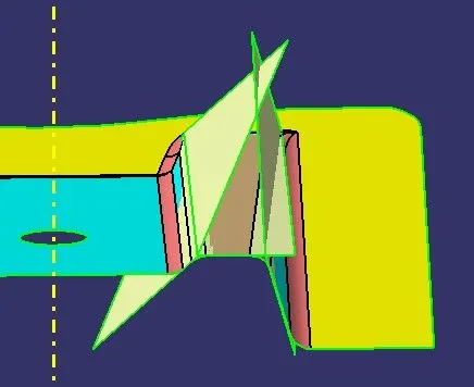
STEP 3: Extrapolating Surfaces
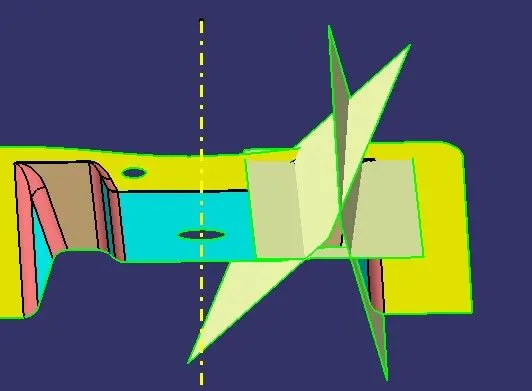
STEP 4: Trimming Required Surfaces.
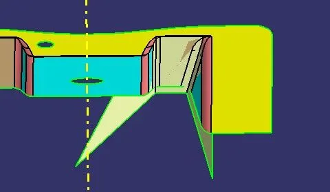
STEP 5: Offset the last trimmed surface to 2.5mm.
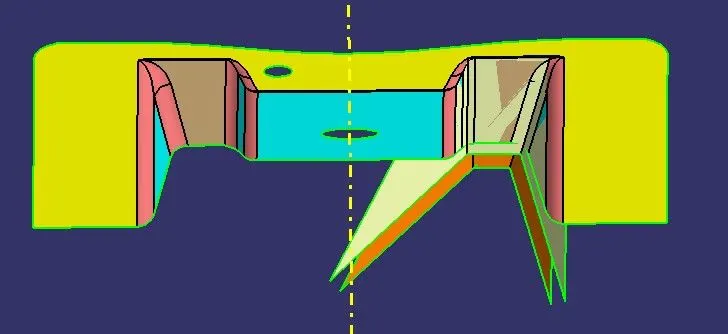
STEP 6: Step 1 to Step 5 repeated for Rib 2.
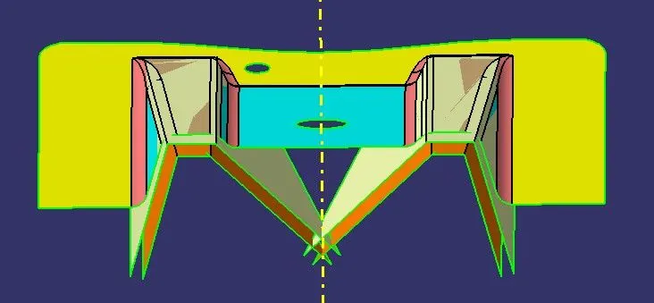
STEP 7: Step 1 to Step 5 repeated for Base Surface.
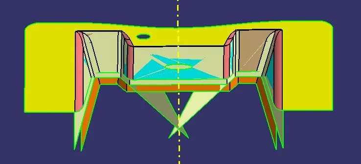
- Whole Component offseted.
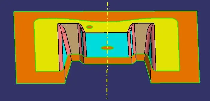
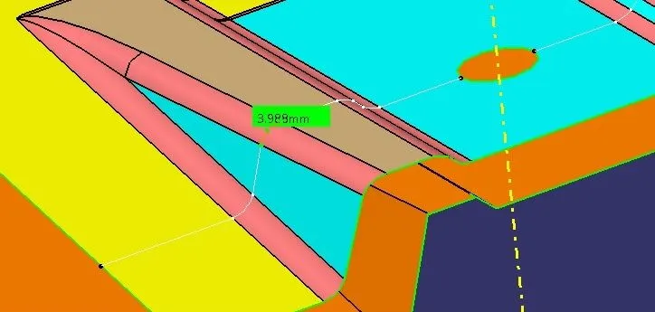
STEP 8: Measure the Edges’s radius with help of intersecting lines.
STEP 9: Assigning radius to all edges in the component with adding radius and thickness of the component.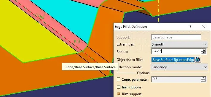
- B SURFACE
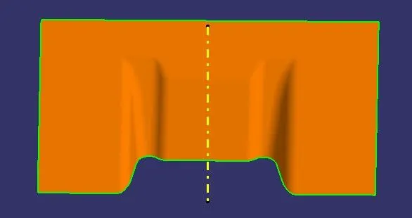
NOW WE HAVE TO CREATE C SURFACE BY FOLLOWING STEPS.
STEP 10 : Create Boundary on A Surface.
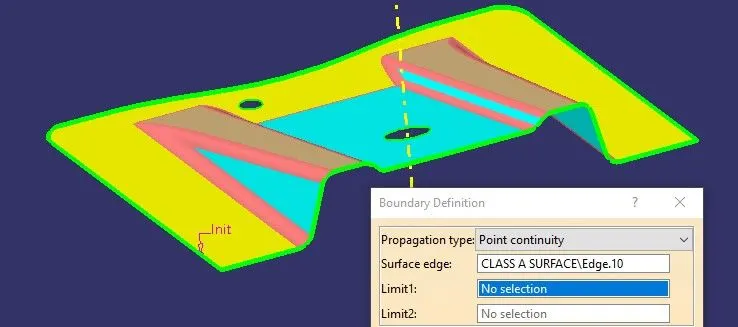
- Extract two more boundaries for the remaining two holes in the component by the same method.
STEP 11: Sweep that boundary with sweep with direction panel.
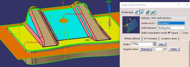
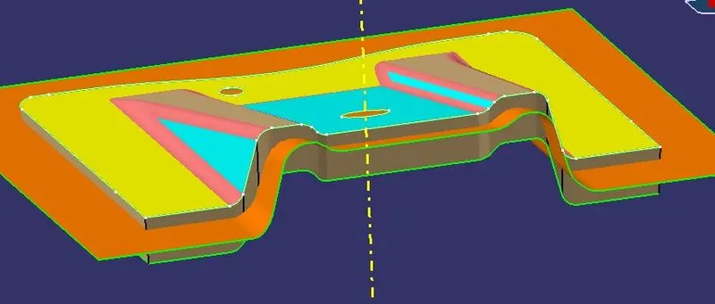
- Extract two more sweeps for the remaining two holes in the component by the same method.
STEP 12 : Join all the three sweeps and A surface.
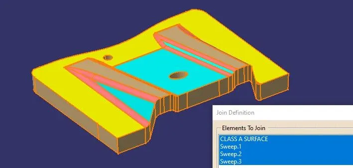
- C SURFACE
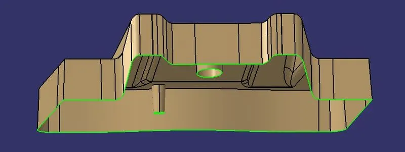
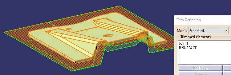
STEP 13: Trim B surface and C Surface.
- This is the final output as a base bracket.
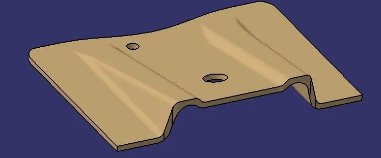
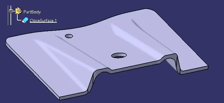
STEP 14: Switch to Part Design Workbench, Define Part body to make it a solid component by surface panel.
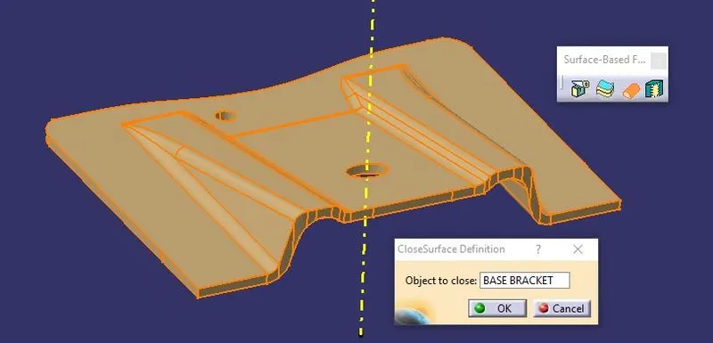
- Part Body
STEP 15 : Check draft analysis on final part body.
- MODEL TREES
Tooling Axis
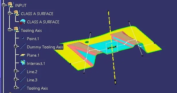
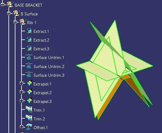
Model Tree for Rib 1
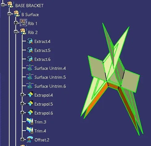
Model Tree for Rib 2
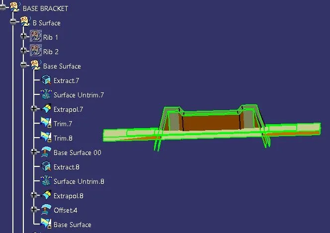
Model Tree for Base Bracket
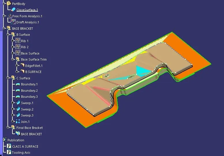
Final Model Tree
__________________________________________________END______________________________________________