Week 8 Challenge
This challenge is to create a ultracapacitor model in which the input will be given as Power demand from energy management system and the outputs to be observed are Ultracapacitor voltage, Current,SOC.
UltraCapacitor modelling:
An ultracapacitor also known as a supercapacitor or electrochemical capacitor is a device for storing electrical energy which is growing rapidly in popularity.
The main equations that are defined in modelling of Ultracapacitor which gives SOC, Voltage and current are
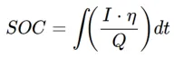
Where
Q = Charge on UC
I = Current
n = Coulomb Efficiency.
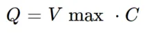
Where
C= Capacitance
Vmax= maximum voltage

Where
R= lumped resistance
Vmax = max. voltage
n = efficiency during the charge-discharge cycle.
PUC = power demand.
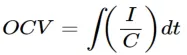
Where
I=Current
C= Capacitance
UC_voltage = (SOC*V_max)-(current*R)
Where
V_max=maximum voltage
R= lumped Resistance
Simulink Model:
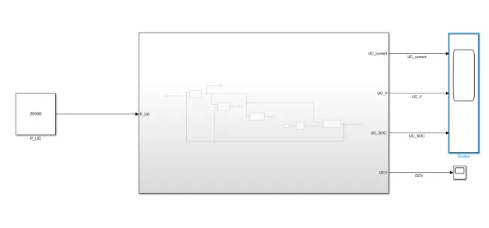
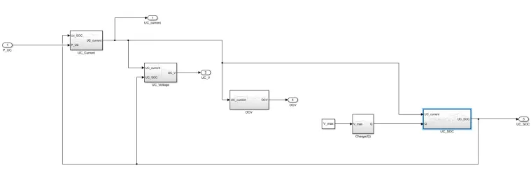
From the above model we can observe that the input given as P_UC which is power demand and the output taken are UC_voltage,UC_current,SOC & OCV. Here the power demand is taken as a constant so we can only observe the discharging of the Ultracapcitor.
By looking into the subsystem we can observe five subsystems which are created according to the ultracapacitor equaitons.
Subsystems:
UC_Current:
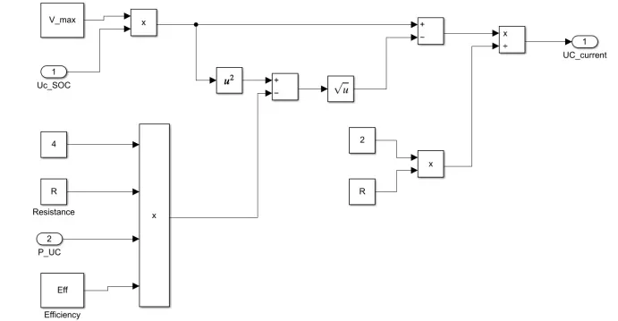
This subsystem inputs are UC_SOC,ultracapacitor maximum voltage value,UC lump resistance value,ultrcapacitor efficiency and finally the power demand(PUC).
Here we can get the UC_current output which is further fed as input to UC_SOC, OCV and UC_Voltage subsystems. And the model is created as per the equation.
The above equation is implemented in simulink model as shown.
UC_Voltage:
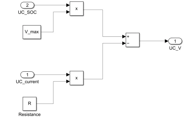
From this subsystem we can get the output as UltraCapacitor Voltage corresponding to the power demand and input taken here are V_max, SOC, R & UC_current. And the subsystem model is created as per the equation.
UC_voltage = (SOC*V_max)-(current*R)
OCV:
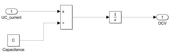
From this subsystem we get the open circuit voltages of ultracapacitor. The input of this subsystem is ultracapacitor current divided by capacitance value and gets integrated over the time to get the output open circuit voltage. And the subsystem model is created as per the equation.
Charge(Q):
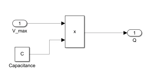
From this subsystem we can get the Charge drawn and supplied to the ultracapacitor corresponding to the power demand. The Charge is estimated by multiplying the Maximum voltage and Capacitance of ultracapacitor.
Q= V_max * C
UC_SOC:
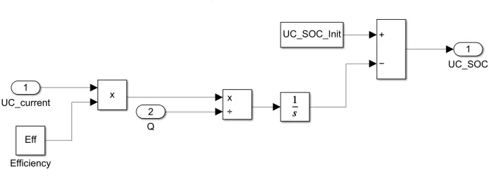
From this block we can get the results of SOC's of ultracapacitor The inputs for this subsystem are UC_Current, Efficiency(Eff), Charge Q.
Here the SOC is subtracted from the initial SOC which is given as 100% or 1. This is to know whether the SOC of Ultracapacitor is increasing or decreasing. And the Subsystem is created as per the SOC equation.
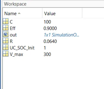
Parameters:
The parameters are initialised and we can observe them in the workspace.
Results:
Current:
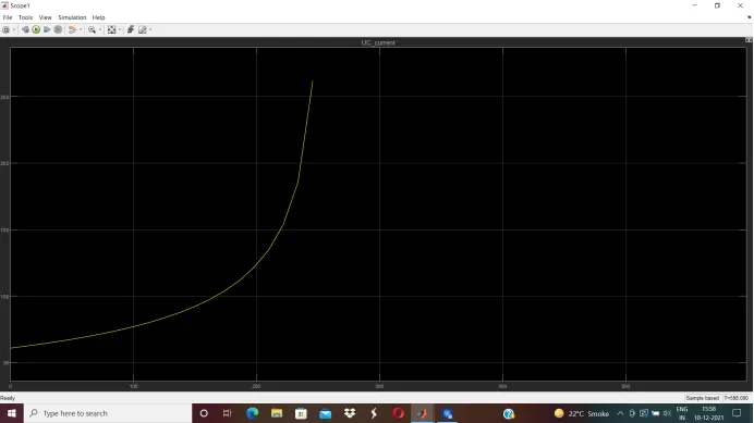
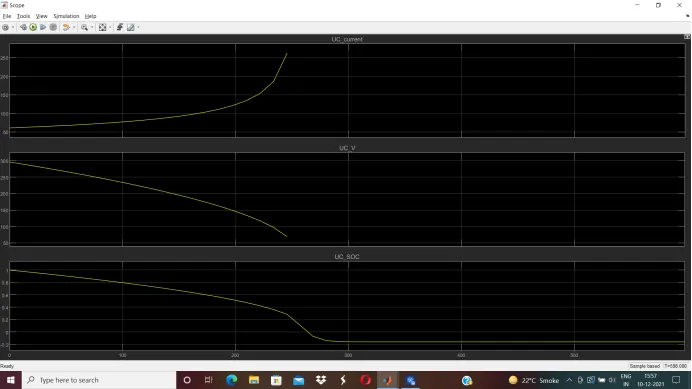
The maximum current supplied from the ultracapacitor is shown and Its seems to rise exponentially once its reaches 50 A .And 260 A is the highest value that capacitor supplied that is observed in the above plot.
Voltage:
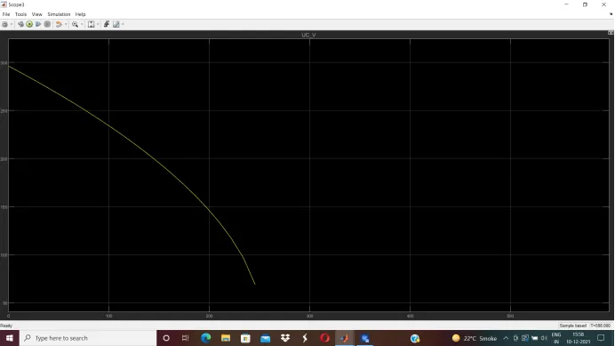
As the discharge mode is considered in this model this is how the voltage graph plot.The max voltage is taken as 300 V . It seems to be decreasing as more current is demanded from UC. And we can observe that it ended up at almost 60V at 20% of SOC.
SOC:
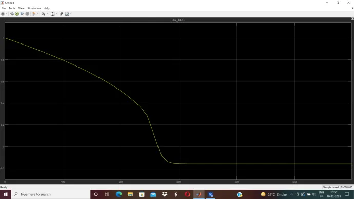
Here we can observe that the SOC is decreasing as we have choosen discharging mode, initially we have given SOC is at 100% at is started from and decreased by almost 260 sec it became 0%.