Week 8 - Challenge 1 - Draft Analysis on a Fan Cover
AIM:
To Create the tooling axis for the given Fan cover model meeting the requirements of the draft angle and perform the Draft analysis on the model.
Draft analysis :
Use of Drafting:
In removal process of molding,part cannot be removed easily because it produces friction between the bodies and damages while removing the molded part.So for smooth removal and damageless component from molding we use drafting.
DRAFTING:
Drafting provides certain angle to the molding part.that angle creates smooth and frictionless removal of the material from molding process.This angle which provides drafting is called draft angle.
Industry recommended drafting angle for the material is 3 deg.
Draft analysis :
The Components which is parallel to the tooling axis cannot be drafted and part will get friction while molding. This friction can be reduced by giving draft angle to each and every corners of the component.this will reduce the friction in the molding process.
Process:
From the given fan cover model I am going to create the tolling axis and Do a draft analysis to that model.
first step : from the provided model we going to check for connexity by using JOIN Option in the toolbar bar.
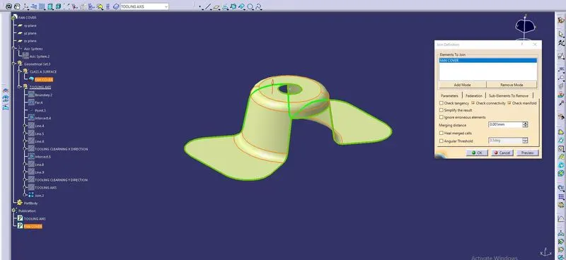
If the check for connexity is passed the component boundary will appear green .which says the component is joined and complete.
second step : Boundary definition
Boundary option in toolbar creates the boundary to the surface which is also shown in green color.but it given boundary line to the surface.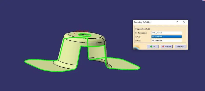
After boundary definition the multi result management will pop up. This option will ask wheather keep all sub- elements , keep the extracted sub- elements and near and far option
the near and far option will give the nearest or farest sub elements present in model.
Near and far sub elements boundaries are selected by near/far definition dialog box
Select the required elements to work with.
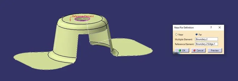
Third step: 3d point is created using point definition dialog box.
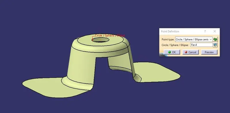
Four step: Axis System is created at the 3d point for creating the intersection
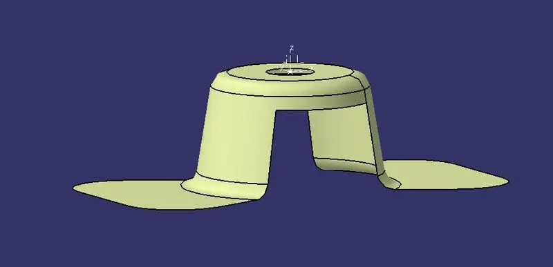
Fifth step: Intersection
Intersection provides tool clearing direction for the component.
The components intersection is created by intersection dialog box: intersection definition
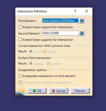
for creating intersection we need two element which are axis system plane and fan cover.
first tooling clearing direction is taken in x axis
so, first element is zx plane and second element is fan cover. this provides the intersection path to the model along x axis
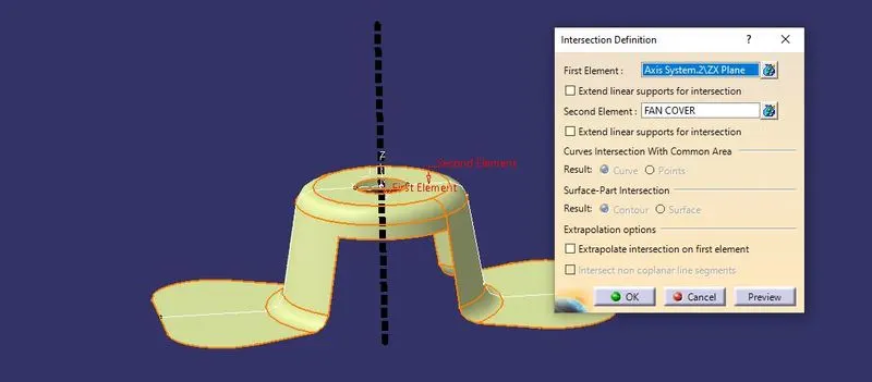
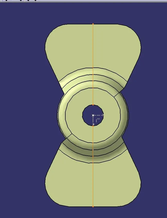
sixth step : creating the line in between the intersection in the 3d point using point direction command.
this line which we created is dummy line which acts as dummy tooling axis.
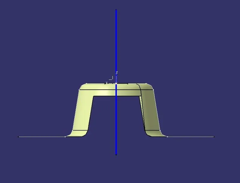
from the taken x direction tool clearing intersect we are going to form the two lines from the surface which are parallel to the tooling axis.
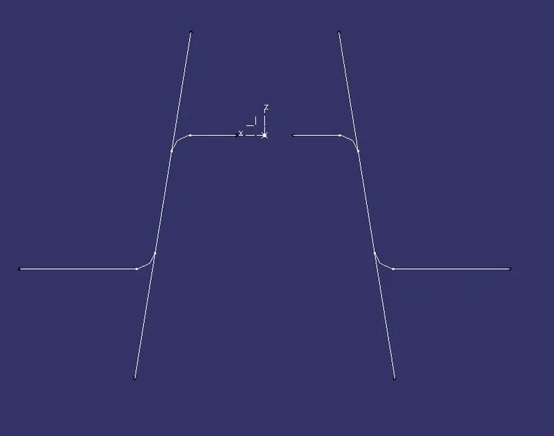
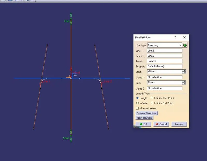
two lines from the intersection are going to create bisecting line. which is going to act as tooling clearing axis in x direction.
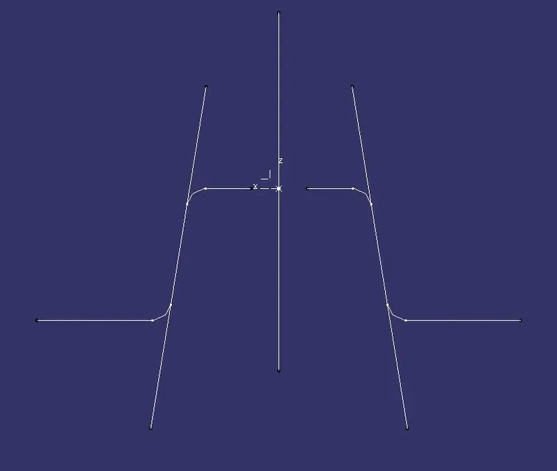
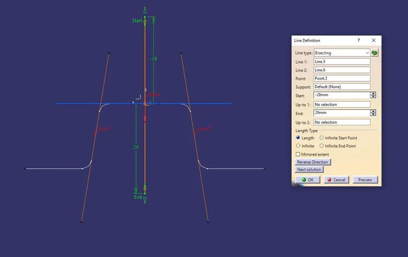
the same intersection are formed along y direction for tool clearing purposes.
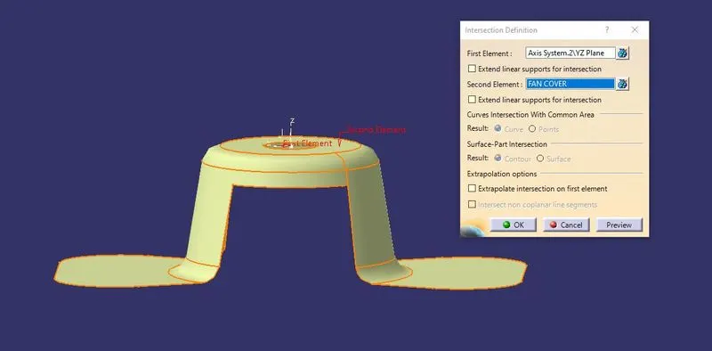
the intersection definition elements are yz plane and fan cover body.
from the taken y direction tool clearing intersect we are going to form the two lines from the surface which are parallel to the tooling axis.
creating the line in between the intersection in the 3d point using point direction command.
this line which we created is dummy line which acts as dummy tooling axis.
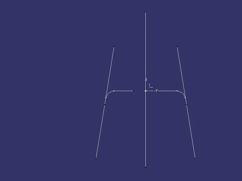
two lines from the intersection are going to create bisecting line. which is going to act as tooling clearing axis in y direction.
from tooling x direction line and tooling y direction line we are going form the bisecting line which is the tooling axis of the model.
seventh step:
tooling axis :
The axis which is formed with tool clearing direction along x and y and bisecting the clearing line intersection surface is called tooling axis.
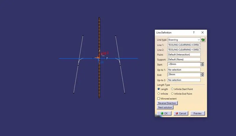
publication :
publication defines and publishes the required geometrical set
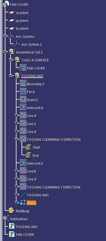
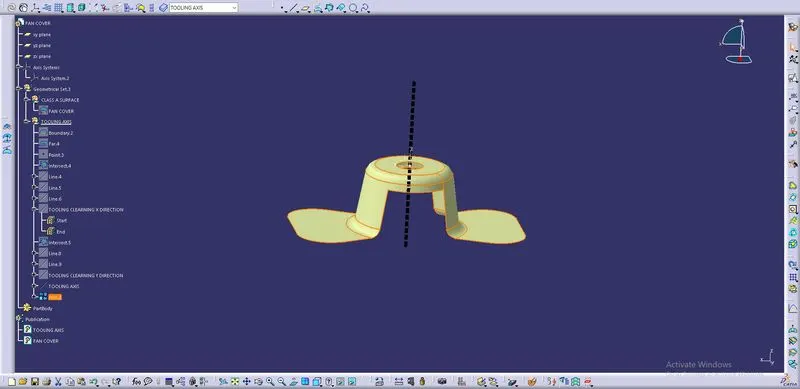
draft analysis:
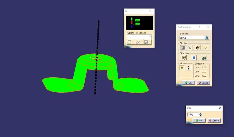
draft analysis dialog box represents the degree of draft . when the draft degree increses above 3 deg which is limit it shows in red colour.
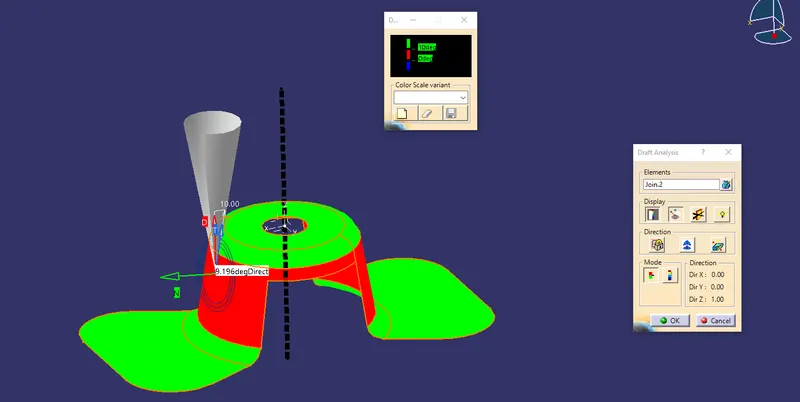
drafting angle should be changed and to industry recommended value of draft angle.
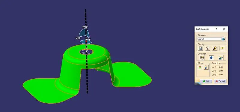
compass is displaced from the normal position to the tooling axis for directing the tooling axis along components surfacing.
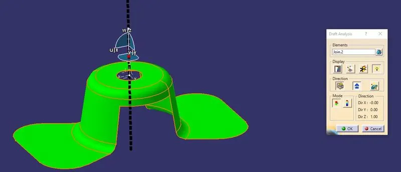
lock option is used for locking the position of tooling axis along the clearing surface.