Week 8 - Challenge 1 - Draft Analysis on a Fan Cover
Draft Analysis on a Fan Cover
AIM:
- To Create the tooling axis for the given Fan cover model meeting the requirements of the draft angle and perform the Draft analysis on the model.
DESCRIPTION:
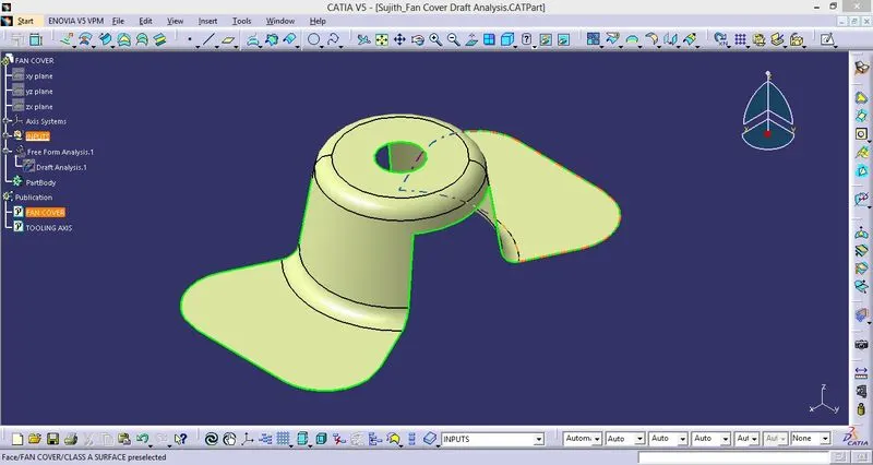
1. CLASS A SURFACE
- The class A surface is the surface created from the concept sketch in the software called AutoDesk ALIAS, the class A surface is basically the styling surface and it is used as reference by the product designer to design the component with the help of tooling axis and draft analysis, here we have fan cover as a class A surface.
2. EVALUATING CLASS A
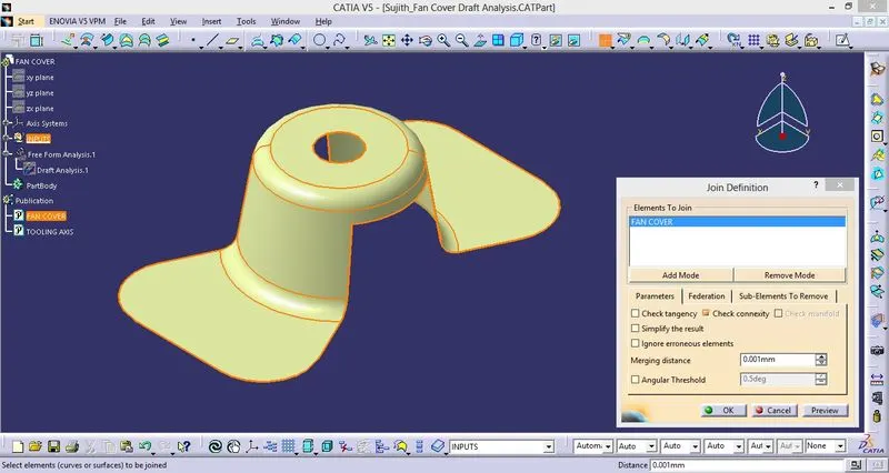
- After receiving the elass A surface the next step is to affirm about the closeness of the class A surface means make sure the class A surface is closed properly and there is no open surface which will hinder the analysis procedure in subsequent processes.
- In catia you can acknowledge this by using the Join and Boundary command.
3. CREATING TOOLING AXIS
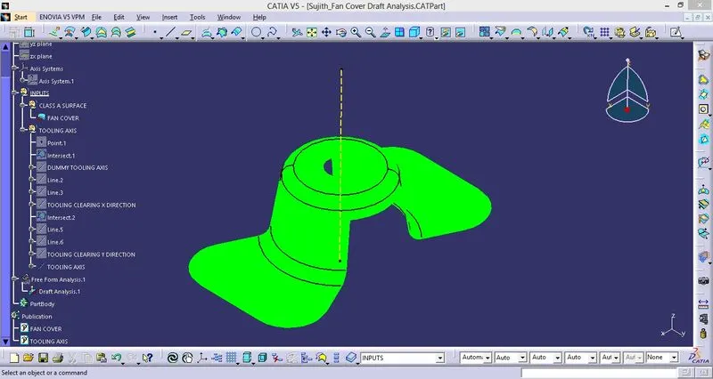
- Find the correct tooling axis where the material don't interfere with the tooling axis and all the elements can be created.
- create an axis system at the centre of the fan cover.
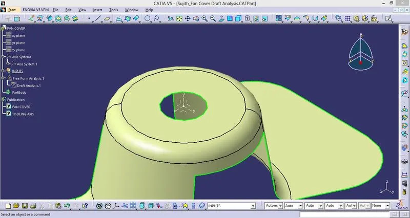
- Intersect the x plane and y planes with respect to the class A surface.
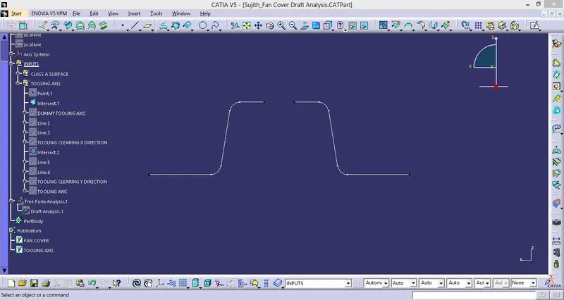
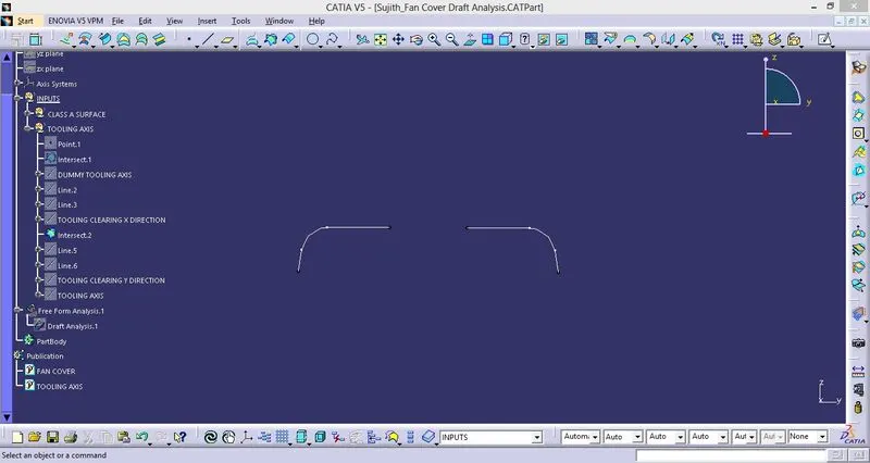
- Hide the class A surface and create point to point lines on the suspected drafts where the draft can interefere with the tooling axis.
- Create a bisecting line with the two lines and point to create a tooling axis of x plane.
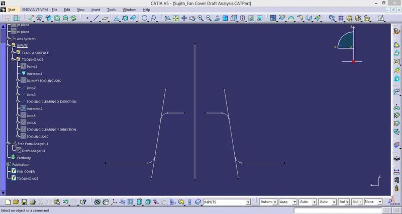
- Follow the above step for Y plane and assign these to different geometric set.
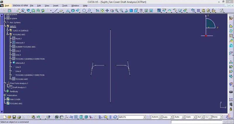
- Now create a bisecting line for the two bisections from plane X and Y in the direction of Z.
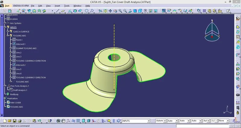
- The tooling axis is created for the component.
- Make it thicker and give a colour for identification and assign it to a geometric set.
4. PUBLICATION
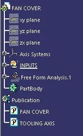
- Publication is done to the component to make it visible and navigate easily.
- To publish the component go to tools »publications and then select the tooling axis and the class A surface.
- A separate tree structure is formed under the main part.
5. DRAFT ANALYSIS
- Before going to drat analysis go to customized view parameter > under mesh > check material and then click ok.
- Now for draft analyses go to insert » analysis » feature draft analysis.
- Use the compass to define the draft direction.
- In the colour scale change the draft angle to 3 degree.
- The component changes to green in indication of passing draft angle.
- Use running point to check the angle on the component.
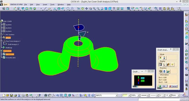
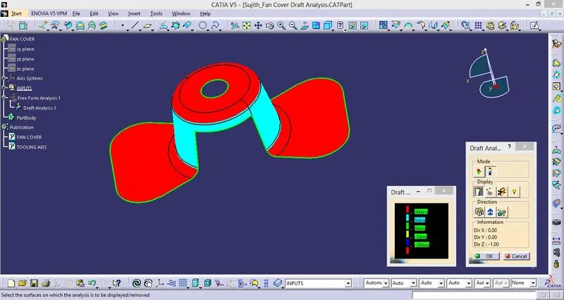
- The Surface passed the draft analysis.
CONCLUSION:
- The tooling axis for the given Fan cover model meeting the requirements of the draft angle is created and the Draft analysis on the model is performed.