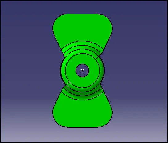
Week 8 - Challenge 1 - Draft Analysis on a Fan Cover
Expanded Tree Structure for Fan Cover
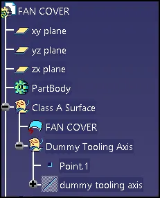
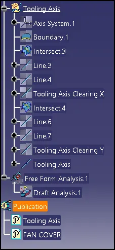
Draft Analysis for Fan Cover
Draft is nothing but providing angle to the surfaces of a component for easy removal of the component from mold.
For doing the Draft analysis an axis is required to be created in the tooling direction i.e in the mould opening direction.
The tooling direction gets decided to depend upon the feasibility of manufacturing of component considering the cost and all the features to be covered during its manufacturing.
In the case of Fan Cover, we have considered the Z direction as the tooling axis.
Steps needed to be followed during the creation of the tooling axis:
- First, consider the tooling axis direction considering the feasibility of manufacturing.
- After that consider the faces which may lead to problems and needed to be analyzed.
- Create a dummy axis in the direction of tooling for reference purposes.
- Create another tooling axis clearing the x-direction for that use intersect command select the respective plane for the intersection.
- Then a curve will be generated by the intersection of surfaces with the plane. Use this curve and draw two lines considering the curve. After that create a line select line type as bisecting, It would create a line bisecting the two lines this the tooling axis in the x-direction.
- Similarly, create another tooling axis in the y-direction.
- Once done with this create a bisecting line by selecting the two lines created in x and y direction passing through a point. This is the main tooling axis.
- Used this axis for the further draft analysis go to Insert-->Analysis--> Feature Draft analysis
- Select the compass place it along the axis created and click on the Class A surface for the draft analysis.
- It will show the result of draft analysis as shown below
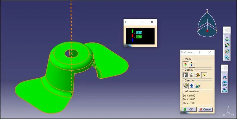
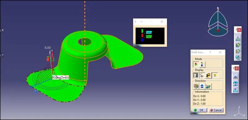
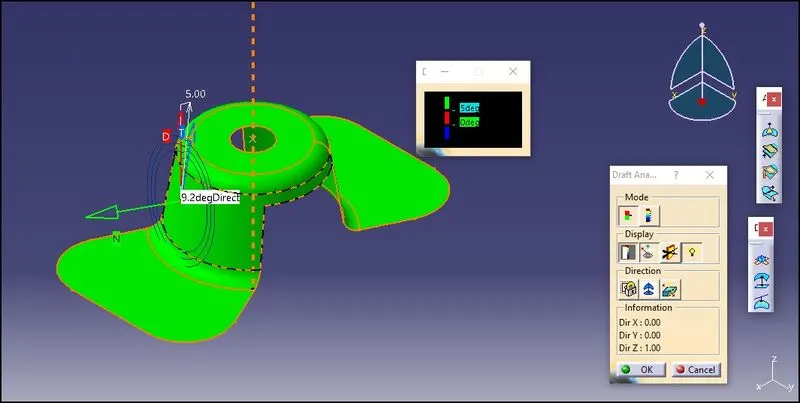
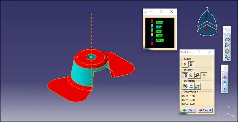
Isometric View
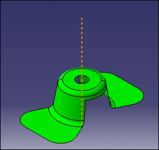
Front View
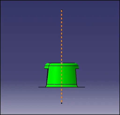
Left Hand View
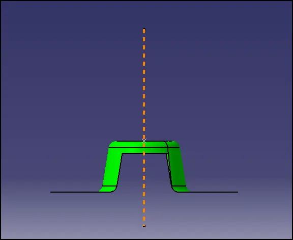
Top View