BOX ASSEMBLY USING NX-CAD
BOX ASSEMBLY USING NX-CAD
- Objective:
- The ultimate aim of this project is to create an assembly of BOX by using NX-CAD software in a sheet metal environment and get familiar with the use of sheet metal features and tools available in NX-CAD.
- To get knowledge of how to apply these features and tools by using software thereby creating complex sheet metal parts.
- Introduction:
In this Project, I have designed the assembly of Box, a sheet metal part by using NX-CAD PLM Software version 10.0. I have explained all the tools and features which are used in this sheet metal part modeling such as tab, flanges, hem flange, bend, bead, mirror, etc. Basically, NX-CAD software can be used for both solid modeling as well as sheet metal modeling but the features which it provides for sheet metal are very handy and feasible to use for the design of complex sheet metal parts.
NX-CAD is a software developed by Siemens, it is a very powerful tool with parametric modeling features for ease and accuracy to model your parts, Siemens NX software is a flexible and powerful integrated solution that helps you deliver better products faster and more efficiently. NX delivers the next generation of design, simulation, and manufacturing solutions that enable companies to realize the value of the digital twin.
Design Methodology of Box assembly :
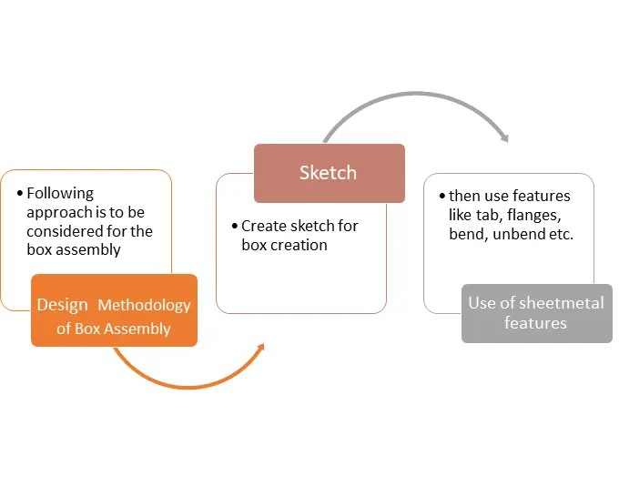
To start with our sheet metal part design first open the NX-CAD software and select the sheet metal as our working environment.
Features use in box assembly :
- Sketch This is the basic or common feature use in any type of modeling but it plays a vital role as it is the foundation of our part model. NX-CAD provides a number of sketch entities and tools for creating sketches such as line, arc, rectangle, spline, circle, ellipse, polygon etc. In the case of our box, I have used sketch entities like rectangles, circles.
- Tab: This feature is used to create a solid body by extruding the sketch along a vector by given thickness value or it is also used to add material along a planar face.
- Flange: This adds a flange along a face at an angle we can change the angle value by providing a bend between a face, this is a very handy feature to create flanges as it propel the bend values which are required to create a flange.
- Normal Cut-Out: This feature cuts or removes material from an existing solid body by projecting the sketch along with the model and then cuts perpendicular the faces which intersects the projecting sketch.
- Bend: It modifies the model by bending it on one side of the drawn sketch line by providing a bend between two sides.
- Closed Corner: It is used to close corners when two adjacent flanges meet at a corner, it does by extending the bends and flanges to a closed corner can be formed.
- Mirror Feature: This is used to mirror the selected features along a plane by selecting the mirror plane from the existing planes, it is a handy tool to replicate our features which are created once and saves time and effort required to recreate that same feature.
- Unbend: It is used to create a flat sheet of our sheet metal model, it does by unbending the bend and material adjacent to the bend.
- Rebend: It again restores the bends which were given to the model previously along with any other features added to the model after unbend.
- Bead: It lifts material along a contour of the sketch thereby acting like a stamping tool.
- Dimple: It is similar to that of the Bead feature this also lifts the area of the model inside the sketch and acts like a stamping tool.
- Hem flange: This feature modifies the edge of the sheet metal by folding it over or onto itself by the creation a flange, it is done for the purpose of safe handling or to provide more stiffness to the sheet metal part.
- Mirror body: It copies a body and mirrors the same body across a plane.
- Unite: This feature combines or unites to separate bodies into a single body.
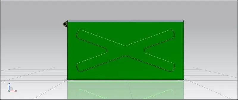
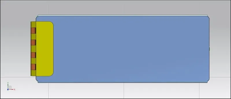
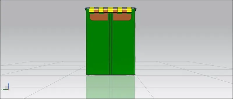
Different Views of Box Assembly
- Front View
- Top View
- Side View
- Isometric View
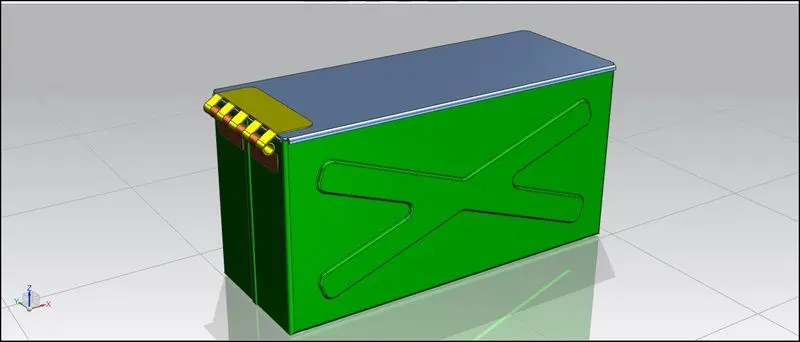
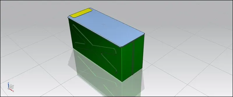
- Drawing Sheet of Box Assembly
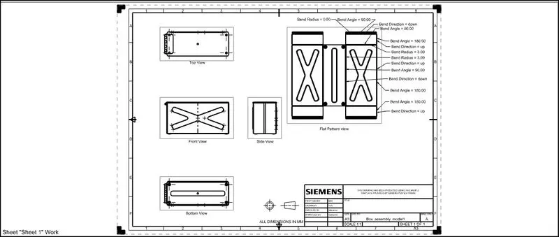
Conclusion: Hence I have completed the design of Box assembly and 2D drafting of the same by the use of NX-CAD software and acquired knowledge of the different tools and features that it provides while working with sheet metal part designing.