Week 8 - Challenge 1 - Draft Analysis on a Fan Cover
AIM:
To perform draft analysis to check if the part has the given draft on its all faces and to determine the tooling axis.
THEORY:
Draft is a tool used in CATIA to make the faces taper with respect to tooling axis. It is the direction of mold part ejection.
PROCEDURE:
1.Merging of class A surface. All surfaces should be connected to no gap should be there we can check it using join command.
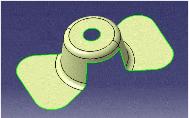
2.We create a dummy tooling line for reference.
3.Now we create tooling clearance along X/Y direction using the intersection of planes with class A surface. We intersect class A surface with XY/YZ/XZ planes and create the reference lines on the surfaces which might face problem during ejection.
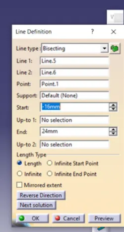
4.We get the tooling direction in both X and Y direction then we use bisecting line to generate the tooling axis.
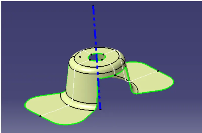
5.Publish the tooling line and class A surface we publish our output so that it can be used for making thick body or class B surface.
DRAFT ANALYSIS:
6.Change the view parameters into custmize mode with material checked.
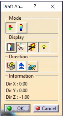
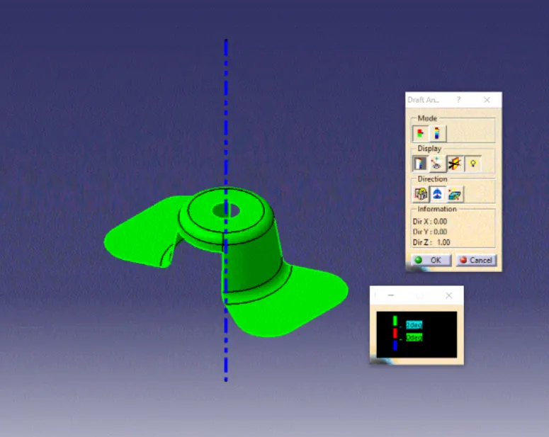
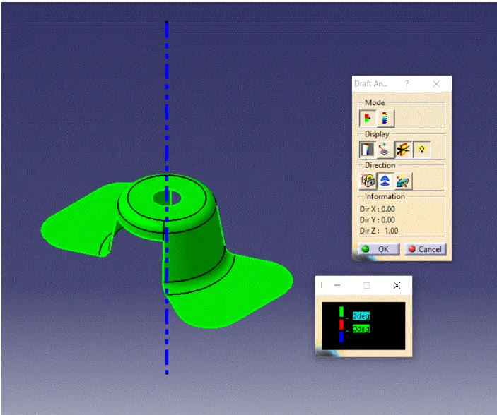
7.Click on the insert toolbar then draft analysis icon. Now draft analysis tool will displays and it shows the information about colour coding mode, Display and Direction.
8.We set the compass on tooling direction once the compass is set on tooling axis we lock it so that it does not change. Also we can flip the direction of the tooling if the compass direction is not as per our tooling direction.
OUTPUT:
1.FINAL DRAFT ANALYSIS:
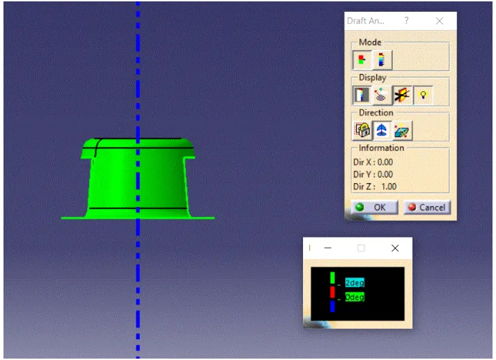
2.FRONT VIEW:
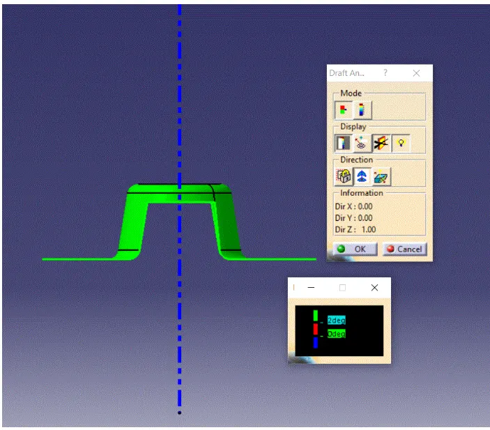
3.SIDE VIEW:
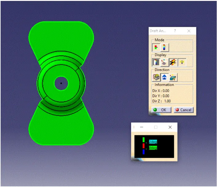
4.TOP VIEW:
5.ISOMETRIC VIEW:
RESULT:
Thus the draft analysis to check if the part has the given draft on its all faces and to determine the tooling axis is performed sucessfully using CATIA.