Week 8 - Challenge 1 - Draft Analysis on a Fan Cover
AIM :
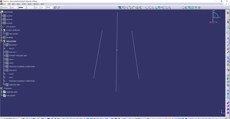
Creating the draft analysis and the tooling axis creation the way of creating the tooling axis particularly the Bisecting
method.
Objective:
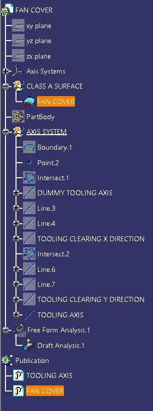
1. To ensure proper tree structure is followed.
2. Geometrical sets should have a proper name based on the sketches present inside of them.
3. All the sketches should be created under the geometrical set.
4. To publish the tooling axis and class-A surface.
Procedure
TOOLING AXIS:
First import the given Class A surface model i.e, Fan cover in CATIA V5.
TREE STRUCTURE:
Draft is the amount of taper for molded or cast parts perpendicular to the parting line. It can be measured in degrees or mm/mm (in/in).
Consider the fabrication of a hollow plastic box, without lid. Once the plastic has hardened around the mold, the mold must be removed. As the plastic hardens, it may contract slightly. By tapering the sides of the mold by an appropriate "draft angle", for instance 2° (two degrees), the mold will be easier to remove. This is a practice that is used, in applicable cases, when working with fiberglass.
If the mold is to be removed from the top, the box should taper in towards the bottom, such that measuring the bottom internal dimension will yield a smaller length and width than measuring the top from which the mold is extracted.
By specifying the opening length and width, a draft angle, and a depth, it is not necessary to specify the dimensions for the internal surface, as these may be calculated from the above.
The manufacture of a part that incorporates zero or negative angles may require a mold that can be separated into two or more parts, in order to release the casting.
DRAFT ANALYSIS:
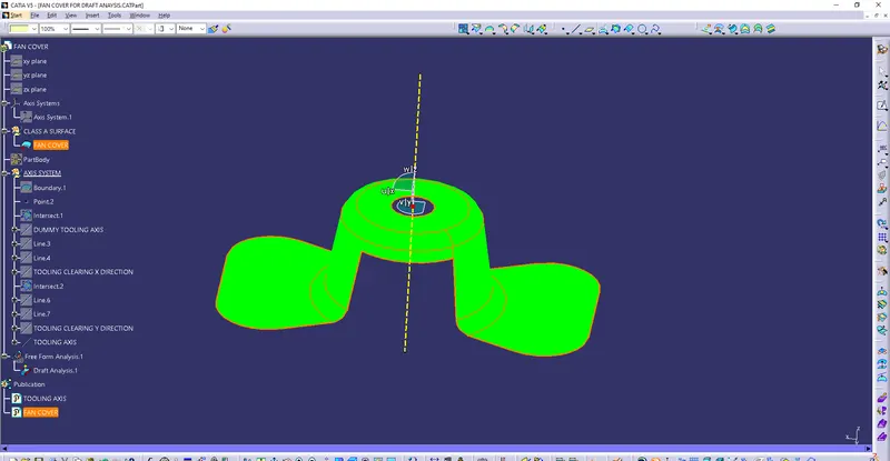
To perform Draft Analysis on the model. Go to menu bar > select insert > Analysis > Feature Draft Analysis.To give the draft direction, use the compass and align Z-axis of it with the tooling axis which we created for the model. Once it is
properly aligned, lock the draft direction. A red colour point will be shown on screen, select the fan cover (CLASS A SURFACE) and it will show us the current draft angle of the model. Set the draft value to 3 deg under the colour scale variant and press Using the Analysis option under Display Tab we can perform the draft analysis on the given model To publish the Tooling Axis and Class A surface (Fan cover) first select it and then Go to menu bar > Tools Publication. This will
publish the Tooling Axis and Class A surface which can be seen in the Tree structure
PHRASES USED:-
DRAFT:
Drafts are defined on molded parts to make them easier to remove from molds
The characteristic elements are
Pulling direction: This direction corresponds to the reference from which the draft faces are defined Draft angle. This is the angle that the draft faces make with the pulling direction, This angle may be defined for each face.
Parting element: This plane face or surface cuts the part in two and each portion is drafted according to its previously defined direction
Neutral element: This element defines a neutral curve on which the drafted face will lie This element will remain the same during the draft. The neutral element and parting element may be the same element.
DRAFT ANALYSIS:
The Draft Analysis command enables you to detect if the part you drafted will be easily removed. This type of analysis is performed based on color ranges identifying zones on the analyzed element where the deviation from the draft direction at any point corresponds to specified values.
TOOLING AXIS:
The Definition tab on the Tool As dialog controls how you want the tool to orient itself whilst cutting a multi-axis toolpath Total as-Select to define the tool orientation. The default value is Vertical which is used for standard 3-axis machining How can be a fund larger continuously changing orientation.
RESULT:
The tooling axis for the given fan cover model is successfully created and draft analysis has also been performed for the same.