Week - 4
1) Washing machine
AIM :
1. To Implement control logic of a “washing machine” using Stateow as per given sequence.
2. Make a Simulink chart for the “Gear shift” logic as per given conditions.
OBJECTIVE :
1. In Simulink, Implement the Control Logic of a Washing Machine using State Flow as per given input conditions. Create a model and Operate the model logic
system and Display the Output of the results by using Lamp Indicator.
2. Create a model for Gear Shifting logic as per given conditions. Give the Speed input while simulation is running and Display the gear number
EXPLANATION :
STUDY - 1:
STATE FLOW : Stateflow provides a graphical language that includes state transition diagrams, ow charts, state transition tables, and truth tables. By using Stateow to
describe how MATLAB algorithms and Simulink models react to input signals, events, and time-based conditions.
CONTROL LOGIC:
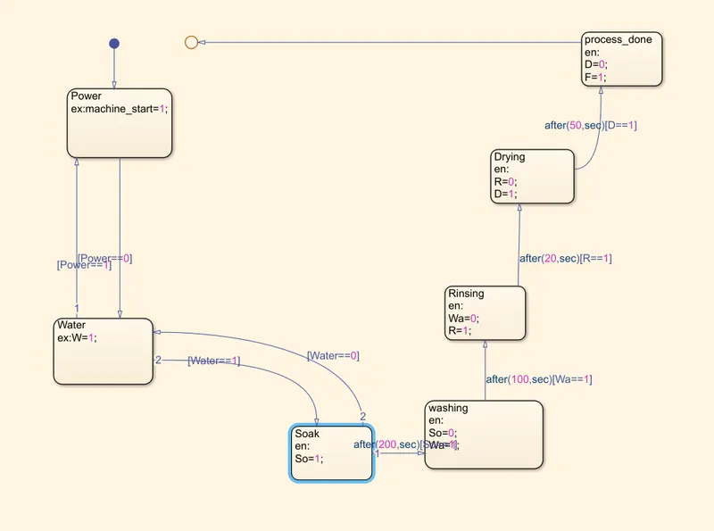
Control Logic is model system logic using State machines,Flowchart and Truth tables.
EXPLANATION FOR CONTROL LOGIC OF A WASHING MACHINE USING STATE FLOW: State Flow is a Simulink tool to implement the state machine. Here model system logic of a Washing Machine using State ow has been done.
STEPS:
Step 1 : Create a chart and enter the given input conditions.
Given Input Conditions :
If the power supply is available, the system gets activated
If the Water supply is not available, stop the process & indicate through LED
Soaking time should be 200s followed by Washing time of 100s.
Then rinsing happens for next 20s & dryer runs for 50s
After all the processes have completed turn on the nished LED
Step 2 : After entering the input conditions in the chart, Go to Symbols pane and assign the given variable. (Example : input data, Output data,etc..)
Step 3 : Give the input values for turning on or off for the Power Supply and Water Supply.
Condition :
if value =1, Power and water Supply will turn On.
if value = 0, Power and water Supply will turn off.
Step 4 : Use 'display' block and 'Lamp' indicator to display the results.
Result:
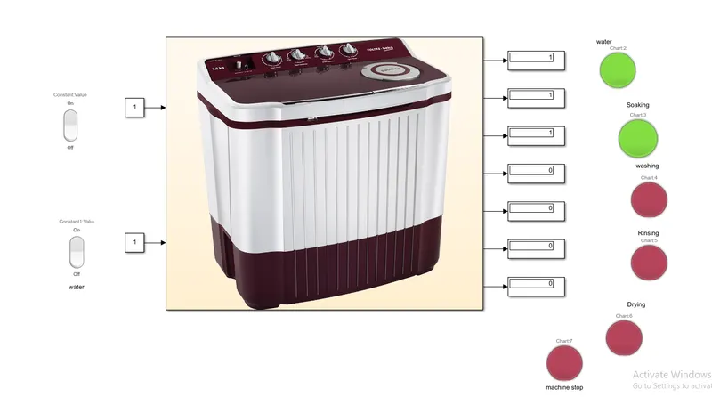
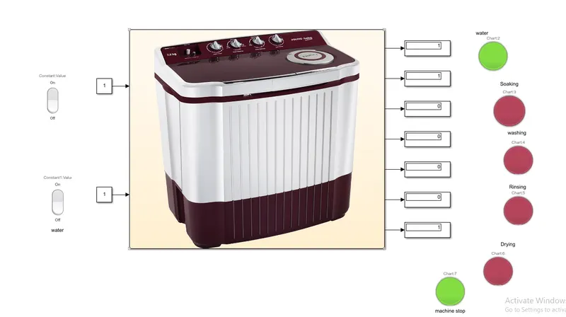
2)Gear shifting mechanism using control logic.
Working:
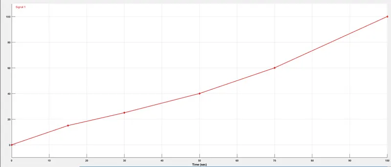
1) The second question is about the working a gear mechanism in a car and at what speeds the gear of a car is changing varying from gear 1 to 5.
2) In the question they have given the speed range in kmph for a particular gear.
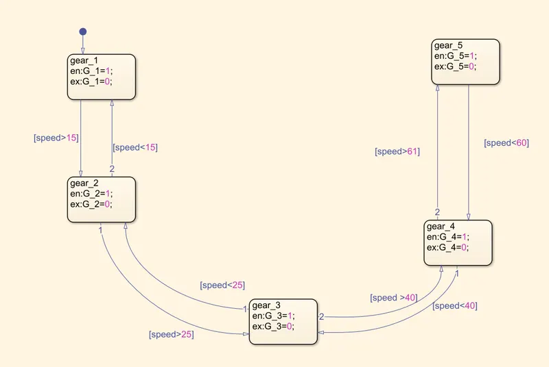
3) We are rst creating a simulink stateow chart for the gear shifting as per variation in speed. In the below image, we see that we are providing varing input as
speed and the gear number ius assigned for a particular speed range if the speed of the vehicle is greater than the earlier gear's speed range the gear is
changed.
4) Then, we provide the inputs which is the speed varing and outputs which is the gear number using the symbols pane in prepare toolstrip.
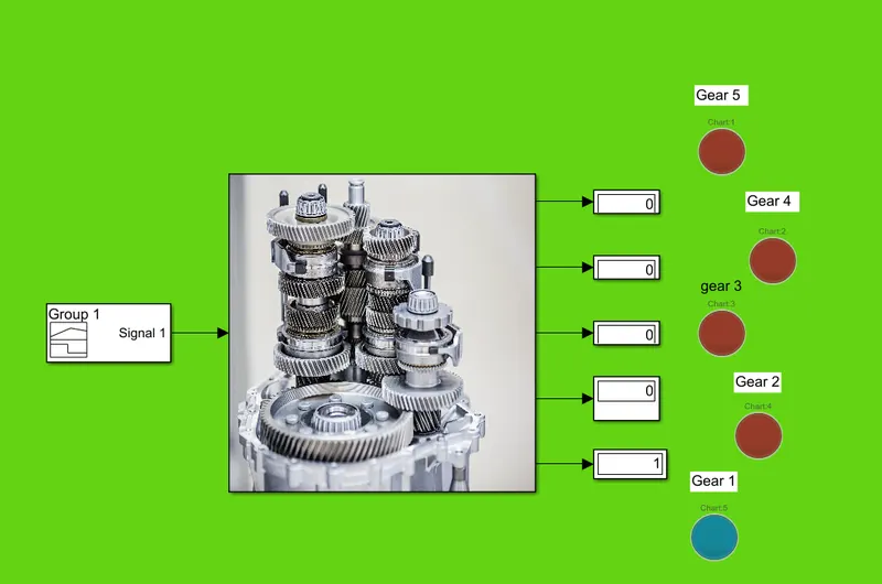
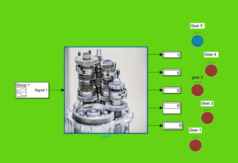
5) We move out of the chart and then we provide a constant varing input with slider gain source as speed and we also display the output using display block
which is basically the gear number. We run the program for innite times hence we provide the stop time as inf. on running we constantly vary the input speed
and corresponding gear for the speed range is displayed as the output as seen in the below images.
Control logic:
Simulation:
Graphical plot:
Conclusion:
1) We have implemented the control logic of a “washing machine” using Stateow using the sequence provided in the aim and after nishing all the processes
the LED light turns green indicating that the process is nished.
2) We have also made a Simulink chart for the “Gear shift” logic as per the information provided in the aim and for the given speed input using the slider gain
block while the simulation is running, the corresponding gear number is displayed as output in the display block.
>>>>>>>>>>>>>>>>>>>>>>>>>>>>>>>>>>>>>>>>>>>>>>>>>END OF REPORT<<<<<<<<<<<<<<<<<<<<<<<<<<<<<<<<<<<<<<<<<<<<<<<<<<