Week 8 - Challenge 1 - Draft Analysis on a Fan Cover
Draft Analysis on a Fan Cover
The Draft Analysis command enables you to detect if the part you drafted will be easily removed. This type of analysis is performed based on color ranges identifying zones on the analyzed element where the deviation from the draft direction at any point, corresponds to specified values.
Draft angle
A draft angle is a taper applied to the vertical walls of the injection molded component to assist with releasing the part from the mold.
Uses of Draft angle
Thermoplastic shrinkage during the cooling process, draft angles greatly reduce friction between the finished, cooled part and the side of the mold. Not only does this create a much easier release process, it offers several other benefits, depending on the design of the part:
• Reduces the chance of damage to the part due to friction during release
• Reduces wear and tear and chances of damage to the mold
• Ensures a uniform, smooth, unscratched finish when required
• Ensures the integrity and uniformity of other surface finishes and textures
• Reduces overall cooling time
Procedure
- Check the connectivity of the given class A surface and use boundary or join operations and ensure that there is no gaps between the surfaces and remove operations after the check
- Create a dummy Tooling axis in a best possible direction as shown in the figure below and we have chosen z axis direction because it doesnt interfere with any part of the surfaces
Tooling axis:
Direction in which the mould opens and closes
dummy Tooling axis
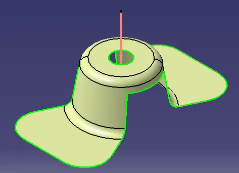
- create an axis system and on the line at suitable point and ensure that it is not in current as shown in the figure
- create an intersect line on zx plane and yz plane and fan component as a result we got two lines as shown in the figure
intersect line on zx plane
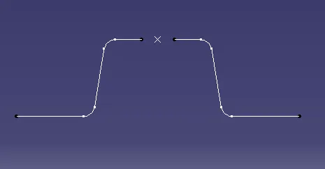
intersect line on yz plane
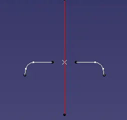
- create an extended line for the each intersect line inorder to avoid the problems of draft angle as show in the fig
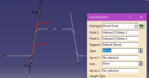
extended line on zx plane
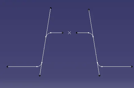
extended line on yz plane
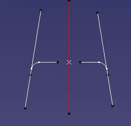
- create a Bisecting line for the extended lines of zx,yz along the center point and named it as Tooling clearance X and Tooling clearance Y
Tooling clearance X
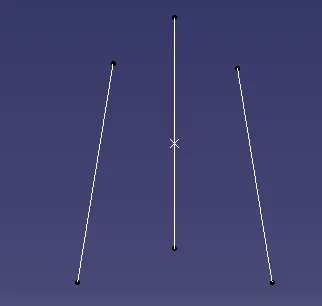
Tooling clearance Y
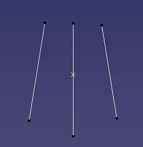
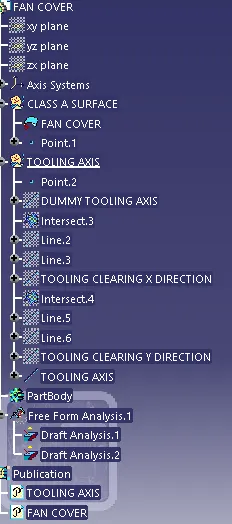
- create a Bisecting line between Tooling clearance X and Tooling clearance Y and named it as tooling axis that was required and publish it using INSERT-PUBLICATION
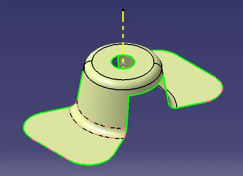
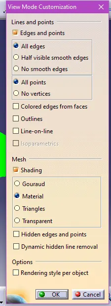
- change the view mode customization to material mode
- Go to INSERT-ANALYSIS-FEATURE DRAFT ANALYSIS and move the compass towards the tooling axis and chnage the range to 3
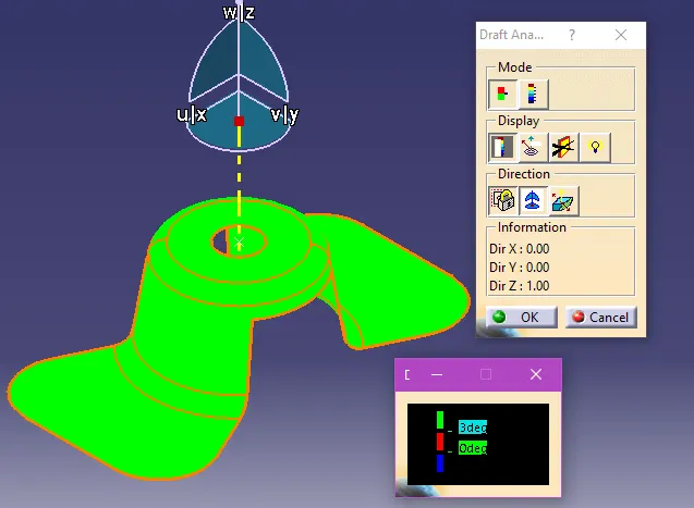
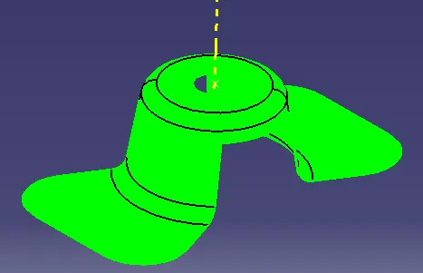
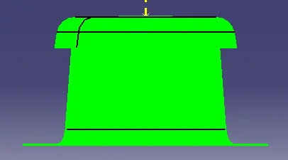
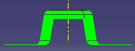
- green colour shows the draft angle having premissable values and draft analysis status of fan cover was passed
isometric view
Front view
side view
prart tree